Cisco AIR-AP1131G-E-K9 Hardware Installation Guide - Page 43
Using the Security Hasp Adapter
 |
View all Cisco AIR-AP1131G-E-K9 manuals
Add to My Manuals
Save this manual to your list of manuals |
Page 43 highlights
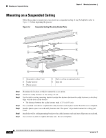
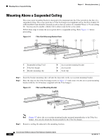
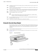
Chapter 3 Mounting Instructions Using the Security Hasp Adapter Step 4 Step 5 Step 6 Step 7 Step 8 Configure the ends of the T-bar box hanger to allow for maximum clearance above the ceiling tile. See the illustration above. Attach the T-rail clips on the each end of the T-bar box hanger to the ceiling grid T-rails. Make sure the clips are securely attached to the T-rails. Connect a drop wire to a building structural element and the hole provided in the bracket mounting clip. This additional support is required in order to comply with the U.S. National Electrical Safety Code. Attach the access point to the access point mounting bracket. Connect the Ethernet cables to the access point. Note The power module and power injector are not rated for mounting above suspended ceilings. Therefore, you must use the Ethernet cable to supply power. Step 9 Step 10 If you need additional security, you can secure the access point to a nearby immovable object using a Kensington lock and security cable. Verify that the access point is operating before replacing the ceiling tile. Using the Security Hasp Adapter The security hasp on the wall or ceiling mounting bracket and the security hasp adapter locks the access point to the bracket to make it more secure. After you have installed the access point on the detachable mounting bracket, follow these steps to secure it with a padlock (Master Lock model 120T, 121T or equivalent). Step 1 Step 2 Connect the Ethernet cable and power jack. Insert the T-shaped tab on the security hasp adapter into the Kensington lock slot on the access point. See Figure 3-6. Figure 3-6 Security Hasp Adapter 81177 OL-4309-07 Cisco Aironet 1100 Series Access Point Hardware Installation Guide 3-7
-
 1
1 -
2
-
3
-
4
-
5
-
6
-
7
-
8
-
9
-
10
-
11
-
12
-
13
-
14
-
15
-
16
-
17
-
18
-
19
-
20
-
21
-
22
-
23
-
24
-
25
-
26
-
27
-
28
-
29
-
30
-
31
-
32
-
33
-
34
-
35
-
36
-
37
-
 38
38 -
 39
39 -
 40
40 -
 41
41 -
 42
42 -
 43
43 -
 44
44 -
 45
45 -
 46
46 -
 47
47 -
 48
48 -
49
-
50
-
51
-
52
-
53
-
54
-
55
-
56
-
57
-
58
-
59
-
60
-
61
-
62
-
63
-
64
-
65
-
66
-
67
-
68
-
69
-
70
-
71
-
72
-
73
-
74
-
75
-
76
-
77
-
78
-
79
-
80
-
81
-
82
-
83
-
84
-
85
-
86
-
87
-
88
-
89
-
90
-
91
-
92
-
93
-
94
-
95
-
96
-
97
-
98
-
99
-
100
-
101
-
102
-
103
-
104
-
105
-
106
-
107
-
108
-
109
-
110
-
111
-
112
-
113
-
114
-
115
-
116
 |
 |
