Cisco AIR-AP1242AG-N-K9 Hardware Installation Guide - Page 131
Access Point Specifications
 |
View all Cisco AIR-AP1242AG-N-K9 manuals
Add to My Manuals
Save this manual to your list of manuals |
Page 131 highlights
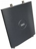
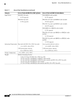
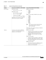
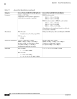
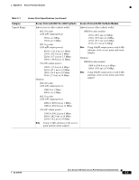
C A P P E N D I X Access Point Specifications This appendix provides technical specifications for the Cisco Aironet 1200 Series Access Point. Table C-1 lists the technical specifications for the access point. Table C-1 Access Point Specifications Category Size Status Indicators Connectors Input Voltage Access Point with 802.11b or 802.11g Radio Access Point with 802.11a Radio Module 6.56 in. W x 7.23 in. D x 1.66 in. H 16.67 cm W x 18.36 cm D x 4.22 cm H With the antenna in the patch position (RM20A and RM21A): 6.56 in. W x 8.04 in. D x 2.21 in. H 16.67 cm W x 20.42 cm D x 5.61 H With the RM22A radio module: 6.56 in. W x 8.76 in. D x 1.66 in. H 16.67 cm W x 22.25 cm D x 4.22 cm H Three indicators on the top panel: Ethernet traffic, status, and radio traffic. Base unit: Back panel (left to right): Left RP-TNC antenna connector; power connector (for plug-in AC power module); RJ-45 connector for 10BASE-T or 100BASE-T Ethernet connections; upside down RJ-45 connector for serial connections; right RP-TNC antenna connector. Front Panel: Card Bus connector used for an 802.11a radio module. RM22A radio module: Left and right RP-TNC antenna connectors 48 VDC nominal. Operational up to 60 VDC. Voltage higher than 60 VDC can damage the unit. OL-4310-05 Cisco Aironet 1200 Series Access Point Hardware Installation Guide C-1
-
 1
1 -
2
-
3
-
4
-
5
-
6
-
7
-
8
-
9
-
10
-
11
-
12
-
13
-
14
-
15
-
16
-
17
-
18
-
19
-
20
-
21
-
22
-
23
-
24
-
25
-
26
-
27
-
28
-
29
-
30
-
31
-
32
-
33
-
34
-
35
-
36
-
37
-
38
-
39
-
40
-
41
-
42
-
43
-
44
-
45
-
46
-
47
-
48
-
49
-
50
-
51
-
52
-
53
-
54
-
55
-
56
-
57
-
58
-
59
-
60
-
61
-
62
-
63
-
64
-
65
-
66
-
67
-
68
-
69
-
70
-
71
-
72
-
73
-
74
-
75
-
76
-
77
-
78
-
79
-
80
-
81
-
82
-
83
-
84
-
85
-
86
-
87
-
88
-
89
-
90
-
91
-
92
-
93
-
94
-
95
-
96
-
97
-
98
-
99
-
100
-
101
-
102
-
103
-
104
-
105
-
106
-
107
-
108
-
109
-
110
-
111
-
112
-
113
-
114
-
115
-
116
-
117
-
118
-
119
-
120
-
121
-
122
-
123
-
124
-
125
-
 126
126 -
 127
127 -
 128
128 -
 129
129 -
 130
130 -
 131
131 -
 132
132 -
 133
133 -
 134
134 -
 135
135 -
 136
136 -
137
-
138
-
139
-
140
-
141
-
142
-
143
-
144
-
145
-
146
-
147
-
148
-
149
-
150
-
151
-
152
-
153
-
154
-
155
-
156
-
157
-
158
-
159
-
160
 |
 |
