Cisco AIR-BR1310G-E-K9 Hardware Installation Guide - Page 95
Table C-1, Access Point, Power Injector, and Power Module Specifications continued
 |
View all Cisco AIR-BR1310G-E-K9 manuals
Add to My Manuals
Save this manual to your list of manuals |
Page 95 highlights
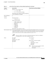
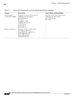
Appendix C Access Point Specifications Table C-1 Access Point, Power Injector, and Power Module Specifications (continued) Category Access Point Power Injector and Power Module Data rates IEEE 802.11b/g-compliant radio: - 1, 2, 5.5 and 11 Mbps 6, 9, 12, 18, 24, 48, and 54 Mbps (Depending on the regulatory domain in which the access point/bridge is installed) Non-overlapping 3 - channels Antenna Integrated antenna - 13-dBi patch array Some external antennas: 5.2-dBi omnidirectional 12-dBi omnidirectional 9-dBi patch 10-dBi yagi 13.5-dBi yagi 14-dBi sector 21-dBi dish (Depending on the regulatory region) Environmental air space Theaccess point/bridge and pow erinjectorprovideadequatefireresistanceand low sm oke-producing characteristicssuitableforoperation in abuilding'senvironm entalairspace,such asabovesuspended ceilings,in accordancew ith Section 300-22(C)oftheN ationalElectricalCode(N EC)and Sections 2-128,12-010(3)and 12-100 oftheCanadian ElectricalCode,Part1,C22.1. Safety Caution The power module is not tested to UL 2043 and should not be placed in a building's air-handling spaces, such as above suspended ceilings. UL 60950 UL 2043 CSA C22.2 No. 60950 IEC 60950 EN 60950 Power injector: UL 2043 Power injector and power module: UL 60950 CSA C22.2 No. 60950 IEC 60950 EN 60950 Note The power injector and power module must be used in an indoor environment. OL-5048-06 Cisco Aironet 1300 Series Wireless Outdoor Access Point/Bridge Hardware Installation Guide C-3
-
 1
1 -
2
-
3
-
4
-
5
-
6
-
7
-
8
-
9
-
10
-
11
-
12
-
13
-
14
-
15
-
16
-
17
-
18
-
19
-
20
-
21
-
22
-
23
-
24
-
25
-
26
-
27
-
28
-
29
-
30
-
31
-
32
-
33
-
34
-
35
-
36
-
37
-
38
-
39
-
40
-
41
-
42
-
43
-
44
-
45
-
46
-
47
-
48
-
49
-
50
-
51
-
52
-
53
-
54
-
55
-
56
-
57
-
58
-
59
-
60
-
61
-
62
-
63
-
64
-
65
-
66
-
67
-
68
-
69
-
70
-
71
-
72
-
73
-
74
-
75
-
76
-
77
-
78
-
79
-
80
-
81
-
82
-
83
-
84
-
85
-
86
-
87
-
88
-
89
-
 90
90 -
 91
91 -
 92
92 -
 93
93 -
 94
94 -
 95
95 -
 96
96 -
 97
97 -
 98
98 -
 99
99 -
 100
100 -
101
-
102
-
103
-
104
-
105
-
106
-
107
-
108
-
109
-
110
-
111
-
112
-
113
-
114
-
115
-
116
-
117
-
118
 |
 |
