Cisco AIR-CB21AG-A-K9 Quick Start Guide - Page 11
Introduction to using, Introduction to using LAN, LANPlanner, Planner - software
 |
View all Cisco AIR-CB21AG-A-K9 manuals
Add to My Manuals
Save this manual to your list of manuals |
Page 11 highlights
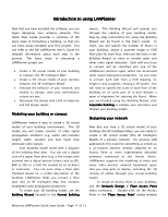
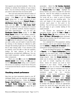
Introduction to using LANPlanner Now that you have installed the software, you can begin designing your wireless network. This Quick Start Guide provides a summary of the basic steps in formatting a building, so that you can more easily complete your first project. You can refer to the full LANPlanner User's Guide for detailed information about each step in the process. The basic steps in executing a LANPlanner project are: • Create a 3D virtual model of your building or campus: the "RF Intelligent Map". • Create a 3D virtual model of your wireless network: the "RF Intelligent Model". • Simulate the behavior of your network, and modify its design, until your performance criteria are met. • Document the design with a bill of materials and full design report. Modeling your building or campus LANPlanner makes it easy to create a 3D virtual model of your building environment. The 3D model you will create consists of radio signal propagation obstacles (e.g. walls) and includes height, width, location and how much they attenuate radio signals. Your building model starts with a diagram of the building floor plan. You can use a digital scan of a paper floor plan (e.g. a fire escape plan scanned into a digital picture format such as JPG, BMP or GIF) or a CAD file created by an architect or contractor. You can even draw a floor plan freehand based on a verbal description of the building. LANPlanner helps you convert a floor plan into an RF Intelligent Map that contains embedded radio propagation properties. To create your 3D building model, use the Building Wizard (located in the Format Building menu). The Building Wizard will prompt you through the creation of your building model. Step-by-step instructions for using the Building Wizard can be found in the User's Guide. In short, you will specify the number of floors in your building, import a scanned image or CAD floor plan for each floor, then use the tools in the Building Wizard to trace or convert walls and other radio signal obstacles. Each wall you trace or convert will be classified into one of the LANPlanner partition types, which has associated radio signal attenuation properties. As you trace or convert each wall from a CAD drawing, its height is also assigned, creating a 3D model. You will need to specify the scale of each floor of the building (or of some part of it) and indicate a point of alignment for stacking the floors. When you are finished using the Building Wizard, click Assemble Building to validate your selections and finalize your building model. Designing your network Now that you have a 3D virtual model of your building (the RF Intelligent Map), you are ready to create a 3D virtual model (The RF Intelligent Model) of a wireless network. For wireless LAN applications this could be something as simple as a co-located antenna directly attached to an Access Point or more sophisticated detached antennas connected to the Access Points. LANPlanner supports the modeling of these and many other wireless network equipment types that you may wish to deploy, including the 3D routing of cables through your virtual building model. To install an Access Point in your building, use the Network Design > Place Access Point menu command. Double-click on the Access Point in the 'Place Access Point' dialog window Motorola LANPlanner Quick Start Guide - Page 11 of 15.
-
 1
1 -
2
-
3
-
4
-
5
-
 6
6 -
 7
7 -
 8
8 -
 9
9 -
 10
10 -
 11
11 -
 12
12 -
 13
13 -
 14
14 -
 15
15
 |
 |