Cisco AIR-LAP1131G-E-K9 Hardware Installation Guide - Page 33
Connecting the Ethernet and Power Cables
 |
View all Cisco AIR-LAP1131G-E-K9 manuals
Add to My Manuals
Save this manual to your list of manuals |
Page 33 highlights
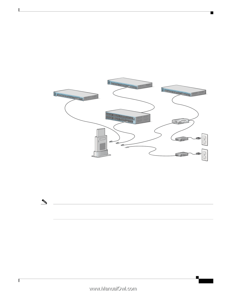
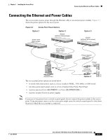
Chapter 2 Installing the Access Point Connecting the Ethernet and Power Cables Connecting the Ethernet and Power Cables The access point receives power through the Ethernet cable or an external power module. Figure 2-3 shows the power options for the access point. Figure 2-3 Access Point Power Options Option 1 Option 2 Switch (without inline power) Switch with inline power SYST RPS STAT UTIL DUPLX SPEED MODE 1 2 3 4 5 6 7 8 9 10 11 10Base-T / 100Base-TX 12 13 14 15 16 17 18 19 20 21 22 23 Catalyst 2950 SERIES 24 21300Base-FX24 SYST RPS STAT UTIL DUPLX SPEED MODE 1 2 3 4 5 6 7 8 9 10 11 10Base-T / 100Base-TX 12 13 14 15 16 17 18 19 20 21 22 23 Catalyst 2950 SERIES 24 100Base-FX 23 24 Inline Power Patch Panel SYST RPS STAT UTIL DUPLX SPEED MODE Option 3 Switch (without inline power) SYST RPS STAT UTIL DUPLX SPEED MODE 1 2 3 4 5 6 7 8 9 10 11 10Base-T / 100Base-TX 12 13 14 15 16 17 18 19 20 21 22 23 Catalyst 2950 SERIES 24 100Base-FX 23 24 Power injector AP/ BRITDOGE NETWOTROK Power cord Universal power supply Access Point Option 4 The access point power options are listed below: • A switch with inline power, such as a Cisco Catalyst 3500XL, 3550, 4000, or 6500 switch • An inline power patch panel, such as a Cisco Catalyst Inline Power Patch Panel • A power injector (Cisco AIR-PWRINJ3= or Cisco AIR-PWRINJ-FIB= ) • A power module (Universal power supply) 81173 81596 Note If you use in-line power from a switch or patch panel, do not connect the power module to the access point. Using two power sources on the access point might cause the switch or patch panel to shut down the port to which the access point is connected. OL-4309-07 Cisco Aironet 1100 Series Access Point Hardware Installation Guide 2-7
-
 1
1 -
2
-
3
-
4
-
5
-
6
-
7
-
8
-
9
-
10
-
11
-
12
-
13
-
14
-
15
-
16
-
17
-
18
-
19
-
20
-
21
-
22
-
23
-
24
-
25
-
26
-
27
-
 28
28 -
 29
29 -
 30
30 -
 31
31 -
 32
32 -
 33
33 -
 34
34 -
 35
35 -
 36
36 -
 37
37 -
 38
38 -
39
-
40
-
41
-
42
-
43
-
44
-
45
-
46
-
47
-
48
-
49
-
50
-
51
-
52
-
53
-
54
-
55
-
56
-
57
-
58
-
59
-
60
-
61
-
62
-
63
-
64
-
65
-
66
-
67
-
68
-
69
-
70
-
71
-
72
-
73
-
74
-
75
-
76
-
77
-
78
-
79
-
80
-
81
-
82
-
83
-
84
-
85
-
86
-
87
-
88
-
89
-
90
-
91
-
92
-
93
-
94
-
95
-
96
-
97
-
98
-
99
-
100
-
101
-
102
-
103
-
104
-
105
-
106
-
107
-
108
-
109
-
110
-
111
-
112
-
113
-
114
-
115
-
116
 |
 |