Cisco AIR-MP21G-A-K9 Hardware Installation Guide - Page 86
Upgrade Overview, Unpacking the Radio Module, Removing the 5-GHz Radio Access Cover
 |
UPC - 746320861081
View all Cisco AIR-MP21G-A-K9 manuals
Add to My Manuals
Save this manual to your list of manuals |
Page 86 highlights
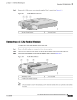
Upgrade Overview Chapter 8 5-GHz Radio Module Upgrade Upgrade Overview This section provides instructions for upgrading the access point 5-GHz radio module (RM20A, RM21A, or RM22A). The following operations summarize the upgrade procedure: 1. Remove all cables and power connections from the access point. 2. Place your access point on a flat surface. 3. For an access point without the 5-GHz radio feature, remove the 5-GHz radio access cover. 4. For an access point with the 5-GHz radio feature, remove the existing 5-GHz radio module. 5. Install the new 5-GHz radio module. Caution Your access point must be running Cisco IOS Release 12.3(2)JA or later before you upgrade to the RM21A or RM22A radio module; otherwise your access point may not be able to complete the boot sequence until the radio is removed. For additional information, refer to the "Finding the Software Version" section. Note After you install the radio module, all configurable radio settings will be at default values. Refer to the Cisco IOS Software Configuration Guide for Cisco Aironet Access Points for complete instructions on configuring the new radio. Unpacking the Radio Module Each 5-GHz radio module is shipped with the following items: • Quick start guide • A product registration card • A T-10 tamper-resistant Torx L-wrench • A 5-GHz radio compliance label • A product compliance label (supplied with RM21A and RM22A radio modules) If anything is missing or damaged, contact your Cisco representative for support. Removing the 5-GHz Radio Access Cover On access points without an installed 5-GHz radio module, you must remove the access cover that covers the 5-GHz radio slot. To remove the 5-GHz radio access cover, follow these steps: Step 1 Remove all cables and power connections from the access point. Step 2 Place the access point on a flat surface so that the unit is upright with the front end facing you. Cisco Aironet 1200 Series Access Point Hardware Installation Guide 8-2 OL-4310-05
-
 1
1 -
2
-
3
-
4
-
5
-
6
-
7
-
8
-
9
-
10
-
11
-
12
-
13
-
14
-
15
-
16
-
17
-
18
-
19
-
20
-
21
-
22
-
23
-
24
-
25
-
26
-
27
-
28
-
29
-
30
-
31
-
32
-
33
-
34
-
35
-
36
-
37
-
38
-
39
-
40
-
41
-
42
-
43
-
44
-
45
-
46
-
47
-
48
-
49
-
50
-
51
-
52
-
53
-
54
-
55
-
56
-
57
-
58
-
59
-
60
-
61
-
62
-
63
-
64
-
65
-
66
-
67
-
68
-
69
-
70
-
71
-
72
-
73
-
74
-
75
-
76
-
77
-
78
-
79
-
80
-
 81
81 -
 82
82 -
 83
83 -
 84
84 -
 85
85 -
 86
86 -
 87
87 -
 88
88 -
 89
89 -
 90
90 -
 91
91 -
92
-
93
-
94
-
95
-
96
-
97
-
98
-
99
-
100
-
101
-
102
-
103
-
104
-
105
-
106
-
107
-
108
-
109
-
110
-
111
-
112
-
113
-
114
-
115
-
116
-
117
-
118
-
119
-
120
-
121
-
122
-
123
-
124
-
125
-
126
-
127
-
128
-
129
-
130
-
131
-
132
-
133
-
134
-
135
-
136
-
137
-
138
-
139
-
140
-
141
-
142
-
143
-
144
-
145
-
146
-
147
-
148
-
149
-
150
-
151
-
152
-
153
-
154
-
155
-
156
-
157
-
158
-
159
-
160
 |
 |
