Cisco CISCO2851 Quick Start Guide - Page 30
Verify the Front Panel LED Indications, Verify the Hardware Configuration, 7 Interface Numbering - image
 |
View all Cisco CISCO2851 manuals
Add to My Manuals
Save this manual to your list of manuals |
Page 30 highlights
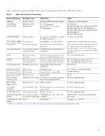
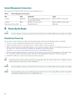
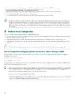
Verify the Front Panel LED Indications The indicator LEDs described in Table 5 provide power, activity, and status information: Table 5 LED Indicators on Front Panel LED Label SYS PWR AUX/ PWR SYS ACT CF LED Color or State Solid green Blinking green Amber Off Green Amber Off Blinking green or solid green Off Green Off Meaning System is operating normally. System is booting or is in ROM monitor mode. System error. Power is off. IP phone power is operating normally (if installed) or Cisco Redundant Power System (RPS) is operating normally (if installed). IP phone power fault (if installed) or Cisco Redundant Power System (RPS) fault (if installed). IP phone power and Cisco RPS are not installed. Packet transfers are occurring. No packet transfers are occurring. CompactFlash memory is being accessed; do not eject. CompactFlash memory is not being accessed; OK to eject. Verify the Hardware Configuration To display and verify the hardware features, enter the following commands: • show version-Displays the system hardware version; the installed software version; the names and sources of configuration files; the boot images; and the amount of installed DRAM, NVRAM, and flash memory. • show diag-Lists and displays diagnostic information about the installed controllers, interface processors, and port adapters. Typical examples are network modules, interface cards (VICs, WICs, HWICs), and advanced integration modules (AIMs). 7 Interface Numbering Table 6 summarizes the interface numbering on a Cisco 2801 series router. Table 7 summarizes the interface numbering on Cisco 2811, Cisco 2821, and Cisco 2851 series routers. Note The interface numbering on Cisco 2800 series routers is different from the numbering on Cisco 2600 series routers. Note On the Cisco 2801 router, the numbering format for slots is interface type 0/slot/port. "0" indicates slots that are built into the chassis of a router. On the Cisco 2801 router, all slots begin with "0," because all slots are built into the chassis. Note that this is different from the Cisco 2811, Cisco 2821, and Cisco 2851 routers. On these routers, some slots are built into the chassis and have slot numbers that begin with "0." However, it is possible to have other slots that are part of a network module or an extension voice module. Those slots have slot numbers that begin with "1" or "2," respectively. 30
-
 1
1 -
2
-
3
-
4
-
5
-
6
-
7
-
8
-
9
-
10
-
11
-
12
-
13
-
14
-
15
-
16
-
17
-
18
-
19
-
20
-
21
-
22
-
23
-
24
-
 25
25 -
 26
26 -
 27
27 -
 28
28 -
 29
29 -
 30
30 -
 31
31 -
 32
32 -
 33
33 -
 34
34 -
 35
35 -
36
-
37
-
38
-
39
-
40
-
41
-
42
-
43
-
44
-
45
-
46
 |
 |
