Cisco CISCO2851 Overview - Page 14
Cisco 2821 and Cisco 2851 Chassis - 2851 ac ip
 |
View all Cisco CISCO2851 manuals
Add to My Manuals
Save this manual to your list of manuals |
Page 14 highlights
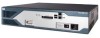
95553 Chassis Views Cisco 2821 and Cisco 2851 Chassis Figure 13, Figure 14, and Figure 15 show the front panel of Cisco 2821 and Cisco 2851 routers. Figure 16 shows the rear panel of a Cisco 2821 router. Figure 17 shows the rear panel of a Cisco 2851 router. Figure 13 Front Panel of Cisco 2821 and Cisco 2851 Routers with AC Input Power and Without IP Phone Power Output 7 6 5 43 2 1 OPTIONAL RPS INPUT 12V 18A SYS AUX/ SYS 1 PWR PWR ACT CF COMPACT FLASH 0 Do Not Remove During Network Operation CONSOLE AUX 100-240 V~ 3A 50/60 Hz 1 Input power connection 2 On/Off switch 3 Console and auxiliary ports 4 Universal serial bus (USB) ports 5 External CompactFlash memory card slot 6 LED indicators 7 Cisco redundant power supply connector (covered if not used) Figure 14 Front Panel of Cisco 2821 and Cisco 2851 Routers with AC Input Power and IP Phone Power Output 7 6 5 43 2 1 OPTIONAL RPS INPUT 12V 18A -48V 8A SYS AUX/ SYS 1 PWR PWR ACT CF COMPACT FLASH 0 Do Not Remove During Network Operation CONSOLE AUX 100-240V~ 8A 50/60 Hz 1 Input power connection 2 On/Off switch 3 Console and auxiliary ports 4 Universal serial bus (USB) ports 5 External CompactFlash memory card slot 6 LED indicators 7 Cisco redundant power supply connector (covered if not used) 95554 Overview of Cisco 2800 Series Routers 14 OL-5783-01
-
 1
1 -
2
-
3
-
4
-
5
-
6
-
7
-
8
-
 9
9 -
 10
10 -
 11
11 -
 12
12 -
 13
13 -
 14
14 -
 15
15 -
 16
16 -
 17
17 -
 18
18 -
 19
19 -
20
-
21
-
22
-
23
-
24
-
25
-
26
 |
 |
