Cisco CISCO3825-AC-IP Hardware Guide - Page 137
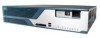
Removing the Power Supply from a Cisco 3845 Router AC Shown, Step 2
 |
View all Cisco CISCO3825-AC-IP manuals
Add to My Manuals
Save this manual to your list of manuals |
Page 137 highlights
Removing and Installing the Fan Tray and Power Supplies in a Cisco 3845 Router Step 2 To remove a power supply, use a flat-blade or number 2 Phillips screwdriver to loosen the two captive thumbscrews. Holding the thumbscrews, rotate the ejector levers on each side of the power supply outward. Fold the handle up, and pull the power supply out by the handle. See Figure 75. An AC power supply is shown as an example. Figure 75 Removing the Power Supply from a Cisco 3845 Router (AC Shown) 117940 1 2 1 2 1 Loosen captive thumbscrews 2 Rotate ejector levers outward Step 3 Step 4 Step 5 Step 6 Make sure that the ejector levers on the new or replacement power supply are extended out away from the power supply. Insert the power supply into the router from the front. The power supply has a built-in connector; you do not need to attach any cables. Rotate the ejector levers inward until the power supply latches into place. Fold down the handle. Use a flat-blade or number 2 Phillips screwdriver to tighten the captive thumbscrews. If necessary, use a flat-blade screwdriver to pry off the plastic panel from the front of the fan tray assembly at the power supply location. Use a number 1 Phillips screwdriver to remove the metal cover plate. Replace the fan tray assembly and tighten the mounting screws. OL-5975-04 Installing and Upgrading Internal Components in Cisco 3800 Series Routers 107
-
 1
1 -
2
-
3
-
4
-
5
-
6
-
7
-
8
-
9
-
10
-
11
-
12
-
13
-
14
-
15
-
16
-
17
-
18
-
19
-
20
-
21
-
22
-
23
-
24
-
25
-
26
-
27
-
28
-
29
-
30
-
31
-
32
-
33
-
34
-
35
-
36
-
37
-
38
-
39
-
40
-
41
-
42
-
43
-
44
-
45
-
46
-
47
-
48
-
49
-
50
-
51
-
52
-
53
-
54
-
55
-
56
-
57
-
58
-
59
-
60
-
61
-
62
-
63
-
64
-
65
-
66
-
67
-
68
-
69
-
70
-
71
-
72
-
73
-
74
-
75
-
76
-
77
-
78
-
79
-
80
-
81
-
82
-
83
-
84
-
85
-
86
-
87
-
88
-
89
-
90
-
91
-
92
-
93
-
94
-
95
-
96
-
97
-
98
-
99
-
100
-
101
-
102
-
103
-
104
-
105
-
106
-
107
-
108
-
109
-
110
-
111
-
112
-
113
-
114
-
115
-
116
-
117
-
118
-
119
-
120
-
121
-
122
-
123
-
124
-
125
-
126
-
127
-
128
-
129
-
130
-
131
-
 132
132 -
 133
133 -
 134
134 -
 135
135 -
 136
136 -
 137
137 -
 138
138
 |
 |
