Cisco CISCO891-K9 Hardware Installation Guide - Page 94
Power and Link, LEDs to Check, Normal Patterns, Table 3-3, Verifying the Router Operation continued
 |
UPC - 882658209178
View all Cisco CISCO891-K9 manuals
Add to My Manuals
Save this manual to your list of manuals |
Page 94 highlights
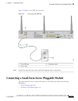
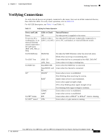
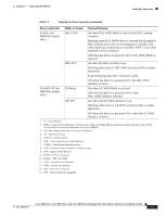
Verifying Connections Chapter 3 Connecting the Router Table 3-3 Verifying the Router Operation (continued) Power and Link LEDs to Check Normal Patterns To wireless LAN WLAN LINK Wireless LAN link status: • Green if at least one client is associated. • Off if no client is associated. WLAN 2.4 GHz Wireless LAN 2.4-GHz status: • Green when radio is connected, SSID13 is configured, signal is being transmitted, and client is associated. • Slow blinking when radio is connected, SSID is configured, and signal is being transmitted. WLAN 5.0 GHz Wireless LAN 5.0-GHz status: • Green when radio is connected, SSID is configured, signal is being transmitted, and client is associated. PoE14 PoE 0 (880 and 890 series only) PoE 1 (880 and 890 series only) PoE 2 (890 series only) • Slow blinking when radio is connected, SSID is configured, and signal is being transmitted. PoE power status: • Green when connected and powered. • Amber when there is a fault with the inline power supply. SFP15 PoE 3 (890 series only) EN Green when the interface is up. S Blinking green indicates port speed. Slow blinking for 100Base SFPs and fast blinking for 1000Base SFPs. To LAN GE/FE line LAN (860VAE models only) Blinking when there is LAN activity (traffic in either direction). Off when the link is down. Cisco 860 Series, Cisco 880 Series, and Cisco 890 Series Integrated Services Routers Hardware Installation Guide 3-38 OL-16193-07
-
 1
1 -
2
-
3
-
4
-
5
-
6
-
7
-
8
-
9
-
10
-
11
-
12
-
13
-
14
-
15
-
16
-
17
-
18
-
19
-
20
-
21
-
22
-
23
-
24
-
25
-
26
-
27
-
28
-
29
-
30
-
31
-
32
-
33
-
34
-
35
-
36
-
37
-
38
-
39
-
40
-
41
-
42
-
43
-
44
-
45
-
46
-
47
-
48
-
49
-
50
-
51
-
52
-
53
-
54
-
55
-
56
-
57
-
58
-
59
-
60
-
61
-
62
-
63
-
64
-
65
-
66
-
67
-
68
-
69
-
70
-
71
-
72
-
73
-
74
-
75
-
76
-
77
-
78
-
79
-
80
-
81
-
82
-
83
-
84
-
85
-
86
-
87
-
88
-
 89
89 -
 90
90 -
 91
91 -
 92
92 -
 93
93 -
 94
94 -
 95
95 -
 96
96 -
 97
97 -
 98
98 -
 99
99 -
100
-
101
-
102
-
103
-
104
-
105
-
106
-
107
-
108
-
109
-
110
-
111
-
112
 |
 |