Cisco CRS-1 Hardware Installation Guide - Page 21
Identifying Slots and Subslots for SIPs and SPAs, SIP Slot Locations on the Cisco CRS-1 Router - 16 slot
 |
View all Cisco CRS-1 manuals
Add to My Manuals
Save this manual to your list of manuals |
Page 21 highlights
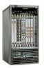
Chapter 2 Overview: Cisco CRS-1 SPA Interface Processor Identifying Slots and Subslots for SIPs and SPAs Identifying Slots and Subslots for SIPs and SPAs The following sections describe SIP, SPA, and interface numbering: • SIP Slot Locations on the Cisco CRS-1 Router, page 2-3 • SPA Slot Numbering on the Cisco CRS-1 SIP-800, page 2-4 • SPA Interface Addresses on SIPs, page 2-6 SIP Slot Locations on the Cisco CRS-1 Router A SIP can be installed in PLIM slots 0 through 15 on the Cisco CRS-1 router 16-slot line card chassis and PLIM slots 0 through 7 on the Cisco CRS-1 router 8-slot line card chassis. Figure 2-2 and Figure 2-3 show the slot numbering on the front (PLIM side) of the line card chassis. Figure 2-2 16-Slot Line Card Chassis Slot Numbers-Front (PLIM) View A0 A1 A2 AM0 PS0 (Power shelf) B0 B1 B2 AM1 PS1 (Power shelf) 0 1 2 3 FC0 FC1 4 5 6 7 Upper PLIM card cage 8 9 10 11 RP0 RP1 12 13 14 15 Lower PLIM card cage 101931 OL-17439-01 Cisco CRS-1 Carrier Routing System SIP and SPA Hardware Installation Guide 2-3
-
 1
1 -
2
-
3
-
4
-
5
-
6
-
7
-
8
-
9
-
10
-
11
-
12
-
13
-
14
-
15
-
 16
16 -
 17
17 -
 18
18 -
 19
19 -
 20
20 -
 21
21 -
 22
22 -
 23
23 -
 24
24 -
 25
25 -
 26
26 -
27
-
28
-
29
-
30
-
31
-
32
-
33
-
34
-
35
-
36
-
37
-
38
-
39
-
40
-
41
-
42
-
43
-
44
-
45
-
46
-
47
-
48
-
49
-
50
-
51
-
52
-
53
-
54
-
55
-
56
-
57
-
58
-
59
-
60
-
61
-
62
-
63
-
64
-
65
-
66
-
67
-
68
-
69
-
70
-
71
-
72
-
73
-
74
-
75
-
76
-
77
-
78
-
79
-
80
-
81
-
82
-
83
-
84
-
85
-
86
-
87
-
88
-
89
-
90
-
91
-
92
-
93
-
94
-
95
-
96
-
97
-
98
-
99
-
100
-
101
-
102
-
103
-
104
 |
 |
