Cisco ME-3400-24FS-A Hardware Installation Guide - Page 13
Cisco ME 3400-24TS AC and DC Switches Front Panel, - me 24ts ac
 |
View all Cisco ME-3400-24FS-A manuals
Add to My Manuals
Save this manual to your list of manuals |
Page 13 highlights
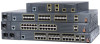
Chapter 1 Product Overview Front Panel Description Cisco ME 3400-24TS AC and DC Switches Front Panel Figure 1-1 shows the Cisco ME 3400G-24TS AC switch front panel. Figure 1-2 shows the Cisco ME 3400G-24TS DC switch front panel. The 10/100 Fast Ethernet ports are grouped in pairs. The first member of the pair (port 1) is above the second member (port 2) on the left. Port 3 is above port 4, and so on. The Gigabit Ethernet uplink SFP module ports are numbered 1 and 2. Figure 1-1 Cisco ME 3400-24TS AC Ethernet Access Switch Front Panel 191300 SYSTEM 1A-01.0R50AA-2,T45IN00GV-60~ HZ CONSOLE 123 12 1X 34 56 78 9 10 11 12 11X 13 14 13X 15 16 17 18 19 20 21 22 2X 23 24 23X 12X 14X 24X 4 Cisco ME 3400 SERIES 1 2 56 7 1 AC power connector 4 10/100 Fast Ethernet ports 7 Cable lock 2 System LED 5 Gigabit Ethernet SFP module ports 3 Console port 6 Ground connector Figure 1-2 Cisco ME 3400-24TS DC Ethernet Access Switch Front Panel 191301 CINUPR+AURTE-N36TB+-2 -72 V - 1A SYSTEM CONSOLE 123 12 1X 34 56 78 9 10 11 12 11X 13 14 13X 15 16 17 18 19 20 21 22 2X 23 24 23X 12X 14X 24X 4 Cisco ME 3400 SERIES 1 2 56 7 1 DC power connector 4 10/100 Fast Ethernet ports 7 Cable lock 2 System LED 5 Gigabit Ethernet SFP module ports 3 Console port 6 Ground connector OL-7677-04 Cisco ME 3400 Ethernet Access Switch Hardware Installation Guide 1-3
-
 1
1 -
2
-
3
-
4
-
5
-
6
-
7
-
 8
8 -
 9
9 -
 10
10 -
 11
11 -
 12
12 -
 13
13 -
 14
14 -
 15
15 -
 16
16 -
 17
17 -
 18
18 -
19
-
20
-
21
-
22
-
23
-
24
-
25
-
26
-
27
-
28
-
29
-
30
-
31
-
32
-
33
-
34
-
35
-
36
-
37
-
38
-
39
-
40
-
41
-
42
-
43
-
44
-
45
-
46
-
47
-
48
-
49
-
50
-
51
-
52
-
53
-
54
-
55
-
56
-
57
-
58
-
59
-
60
-
61
-
62
-
63
-
64
-
65
-
66
-
67
-
68
-
69
-
70
-
71
-
72
-
73
-
74
-
75
-
76
-
77
-
78
-
79
-
80
-
81
-
82
-
83
-
84
-
85
-
86
-
87
-
88
 |
 |
