Cisco WS-C2960-24PC-L Software Guide - Page 234
Q Trunk Restrictions, Trunking Method, Catalyst 4000, Series
 |
UPC - 882658169328
View all Cisco WS-C2960-24PC-L manuals
Add to My Manuals
Save this manual to your list of manuals |
Page 234 highlights
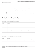
Understanding How VLAN Trunks Work Chapter 11 Configuring VLAN Trunks on Fast Ethernet and Gigabit Ethernet Ports Table 11-4 Trunking Encapsulation Support Trunking Method ISL 802.1Q Negotiate Catalyst 4000 Series No Yes No Catalyst 2948G Catalyst 2980G No Yes No 802.1Q Trunk Restrictions This section lists the configuration guidelines and restrictions for using 802.1Q trunks to impose some limitations on the trunking strategy for a network. These restrictions apply when using 802.1Q trunks: • For a trunk to come up and work, you must physically connect the trunk port to another network device. • When using VTP to carry VLANs over the trunk port, you must manually configure extended VLANs on each switch, because VTP carries only VLANs 1−1005. • When connecting Cisco switches through an 802.1Q trunk, make sure that the native VLAN for an 802.1Q trunk is the same on both ends of the trunk link. If the native VLAN on one end of the trunk is different from the native VLAN on the other end, spanning tree loops can result. • Disabling spanning tree on the native VLAN of an 802.1Q trunk without disabling spanning tree on every VLAN in the network can cause spanning-tree loops. We recommend that you leave spanning tree enabled on the native VLAN of an 802.1Q trunk. If this is not possible, disable spanning tree on every VLAN in the network. Make sure that your network is free of physical loops before disabling spanning tree. • When you connect two Cisco switches through 802.1Q trunks, the switches exchange spanning-tree BPDUs on each VLAN allowed on the trunks. The BPDUs on the native VLAN of the trunk are sent untagged to the reserved IEEE 802.1d spanning-tree multicast MAC address (01-80-C2-00-00-00). The BPDUs on all other VLANs on the trunk are sent tagged to the reserved Cisco Shared Spanning Tree (SSTP) multicast MAC address (01-00-0c-cc-cc-cd). • Non-Cisco 802.1Q switches maintain only a single instance of spanning tree (the Mono Spanning Tree, or MST) that defines the spanning-tree topology for all VLANs. When you connect a Cisco switch to a non-Cisco switch through an 802.1Q trunk, the MST of the non-Cisco switch and the native VLAN spanning-tree of the Cisco switch combine to form a single spanning-tree topology known as the Common Spanning Tree (CST). • Because Cisco switches transmit BPDUs to the SSTP multicast MAC address on VLANs other than the native VLAN of the trunk, non-Cisco switches do not recognize these frames as BPDUs and flood them on all ports in the corresponding VLAN. Other Cisco switches connected to the non-Cisco 802.1Q cloud receive these flooded BPDUs. This allows Cisco switches to maintain a per-VLAN spanning-tree topology across a cloud of non-Cisco 802.1Q switches. The non-Cisco 802.1Q cloud separating the Cisco switches is treated as a single broadcast segment between all switches connected to the non-Cisco 802.1Q cloud through 802.1Q trunks. • Make sure that the native VLAN is the same on all of the 802.1Q trunks connecting the Cisco switches to the non-Cisco 802.1Q cloud. 11-4 Catalyst 4500 Series, Catalyst 2948G, Catalyst 2980G Switches Software Configuration Guide-Release 8.1 78-15486-01
-
 1
1 -
2
-
3
-
4
-
5
-
6
-
7
-
8
-
9
-
10
-
11
-
12
-
13
-
14
-
15
-
16
-
17
-
18
-
19
-
20
-
21
-
22
-
23
-
24
-
25
-
26
-
27
-
28
-
29
-
30
-
31
-
32
-
33
-
34
-
35
-
36
-
37
-
38
-
39
-
40
-
41
-
42
-
43
-
44
-
45
-
46
-
47
-
48
-
49
-
50
-
51
-
52
-
53
-
54
-
55
-
56
-
57
-
58
-
59
-
60
-
61
-
62
-
63
-
64
-
65
-
66
-
67
-
68
-
69
-
70
-
71
-
72
-
73
-
74
-
75
-
76
-
77
-
78
-
79
-
80
-
81
-
82
-
83
-
84
-
85
-
86
-
87
-
88
-
89
-
90
-
91
-
92
-
93
-
94
-
95
-
96
-
97
-
98
-
99
-
100
-
101
-
102
-
103
-
104
-
105
-
106
-
107
-
108
-
109
-
110
-
111
-
112
-
113
-
114
-
115
-
116
-
117
-
118
-
119
-
120
-
121
-
122
-
123
-
124
-
125
-
126
-
127
-
128
-
129
-
130
-
131
-
132
-
133
-
134
-
135
-
136
-
137
-
138
-
139
-
140
-
141
-
142
-
143
-
144
-
145
-
146
-
147
-
148
-
149
-
150
-
151
-
152
-
153
-
154
-
155
-
156
-
157
-
158
-
159
-
160
-
161
-
162
-
163
-
164
-
165
-
166
-
167
-
168
-
169
-
170
-
171
-
172
-
173
-
174
-
175
-
176
-
177
-
178
-
179
-
180
-
181
-
182
-
183
-
184
-
185
-
186
-
187
-
188
-
189
-
190
-
191
-
192
-
193
-
194
-
195
-
196
-
197
-
198
-
199
-
200
-
201
-
202
-
203
-
204
-
205
-
206
-
207
-
208
-
209
-
210
-
211
-
212
-
213
-
214
-
215
-
216
-
217
-
218
-
219
-
220
-
221
-
222
-
223
-
224
-
225
-
226
-
227
-
228
-
 229
229 -
 230
230 -
 231
231 -
 232
232 -
 233
233 -
 234
234 -
 235
235 -
 236
236 -
 237
237 -
 238
238 -
 239
239 -
240
-
241
-
242
-
243
-
244
-
245
-
246
-
247
-
248
-
249
-
250
-
251
-
252
-
253
-
254
-
255
-
256
-
257
-
258
-
259
-
260
-
261
-
262
-
263
-
264
-
265
-
266
-
267
-
268
-
269
-
270
-
271
-
272
-
273
-
274
-
275
-
276
-
277
-
278
-
279
-
280
-
281
-
282
-
283
-
284
-
285
-
286
-
287
-
288
-
289
-
290
-
291
-
292
-
293
-
294
-
295
-
296
-
297
-
298
-
299
-
300
-
301
-
302
-
303
-
304
-
305
-
306
-
307
-
308
-
309
-
310
-
311
-
312
-
313
-
314
-
315
-
316
-
317
-
318
-
319
-
320
-
321
-
322
-
323
-
324
-
325
-
326
-
327
-
328
-
329
-
330
-
331
-
332
-
333
-
334
-
335
-
336
-
337
-
338
-
339
-
340
-
341
-
342
-
343
-
344
-
345
-
346
-
347
-
348
-
349
-
350
-
351
-
352
-
353
-
354
-
355
-
356
-
357
-
358
-
359
-
360
-
361
-
362
-
363
-
364
-
365
-
366
-
367
-
368
-
369
-
370
-
371
-
372
-
373
-
374
-
375
-
376
-
377
-
378
-
379
-
380
-
381
-
382
-
383
-
384
-
385
-
386
-
387
-
388
-
389
-
390
-
391
-
392
-
393
-
394
-
395
-
396
-
397
-
398
-
399
-
400
-
401
-
402
-
403
-
404
-
405
-
406
-
407
-
408
-
409
-
410
-
411
-
412
-
413
-
414
-
415
-
416
-
417
-
418
-
419
-
420
-
421
-
422
-
423
-
424
-
425
-
426
-
427
-
428
-
429
-
430
-
431
-
432
-
433
-
434
-
435
-
436
-
437
-
438
-
439
-
440
-
441
-
442
-
443
-
444
-
445
-
446
-
447
-
448
-
449
-
450
-
451
-
452
-
453
-
454
-
455
-
456
-
457
-
458
-
459
-
460
-
461
-
462
-
463
-
464
-
465
-
466
-
467
-
468
-
469
-
470
-
471
-
472
-
473
-
474
-
475
-
476
-
477
-
478
-
479
-
480
-
481
-
482
-
483
-
484
-
485
-
486
-
487
-
488
-
489
-
490
-
491
-
492
-
493
-
494
-
495
-
496
-
497
-
498
-
499
-
500
-
501
-
502
-
503
-
504
-
505
-
506
-
507
-
508
-
509
-
510
-
511
-
512
-
513
-
514
-
515
-
516
-
517
-
518
-
519
-
520
-
521
-
522
-
523
-
524
-
525
-
526
-
527
-
528
-
529
-
530
-
531
-
532
-
533
-
534
-
535
-
536
-
537
-
538
-
539
-
540
-
541
-
542
-
543
-
544
-
545
-
546
-
547
-
548
-
549
-
550
-
551
-
552
-
553
-
554
-
555
-
556
-
557
-
558
-
559
-
560
-
561
-
562
-
563
-
564
-
565
-
566
-
567
-
568
-
569
-
570
-
571
-
572
-
573
-
574
-
575
-
576
-
577
-
578
-
579
-
580
-
581
-
582
-
583
-
584
-
585
-
586
-
587
-
588
-
589
-
590
-
591
-
592
-
593
-
594
-
595
-
596
-
597
-
598
-
599
-
600
-
601
-
602
-
603
-
604
-
605
-
606
-
607
-
608
-
609
-
610
-
611
-
612
 |
 |