Cisco WS-C2960S-48LPS-L Hardware Installation Guide - Page 31
Cisco RPS 675, Console Port, Security Slots
 |
View all Cisco WS-C2960S-48LPS-L manuals
Add to My Manuals
Save this manual to your list of manuals |
Page 31 highlights
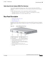
Chapter 1 Product Overview Rear Panel Description • List the connected switches and the power-supply module sizes • Obtain reports when a switch is powered by the RPS • Obtain status reports for the RPS power-supply module • Read and monitor backup, failure, and exception history Cisco RPS 675 The Cisco 675 RPS is a redundant power system that supports six network devices and provides power to one failed switch at a time. It automatically senses when the internal power supply of a connected switch fails and provides power to the failed switch, preventing loss of network traffic. The Cisco RPS 675 has two output levels: -48 V and 12 V. The total maximum output power is 675 W. Console Port You can connect the switch to a PC by means of the console port and the supplied RJ-45-to-DB-9 female cable. If you want to connect the switch console port to a terminal, you need to provide an RJ-45-to-DB-25 female DTE adapter. You can order a kit (part number ACS-DSBUASYN=) containing that adapter from Cisco. For console port and adapter pinout information, see the "Connector and Cable Specifications" section on page B-1. Note The console port on the Catalyst 2960 8-port switches is on the front panel rather than on the rear panel. Security Slots The Catalyst 2960 8-port switches have security slots on the left and right side panels. You can install an optional cable lock, such as the type that is used to secure a laptop computer, to secure either or both sides of the switch. Figure 1-26 shows the slot on a left-side panel. Figure 1-26 Switch Left Panel 204628 1 1 Security slot OL-7075-09 Catalyst 2960 Switch Hardware Installation Guide 1-21
-
 1
1 -
2
-
3
-
4
-
5
-
6
-
7
-
8
-
9
-
10
-
11
-
12
-
13
-
14
-
15
-
16
-
17
-
18
-
19
-
20
-
21
-
22
-
23
-
24
-
25
-
 26
26 -
 27
27 -
 28
28 -
 29
29 -
 30
30 -
 31
31 -
 32
32 -
 33
33 -
 34
34 -
 35
35 -
 36
36 -
37
-
38
-
39
-
40
-
41
-
42
-
43
-
44
-
45
-
46
-
47
-
48
-
49
-
50
-
51
-
52
-
53
-
54
-
55
-
56
-
57
-
58
-
59
-
60
-
61
-
62
-
63
-
64
-
65
-
66
-
67
-
68
-
69
-
70
-
71
-
72
-
73
-
74
-
75
-
76
-
77
-
78
-
79
-
80
-
81
-
82
-
83
-
84
-
85
-
86
-
87
-
88
-
89
-
90
-
91
-
92
-
93
-
94
-
95
-
96
-
97
-
98
-
99
-
100
-
101
-
102
-
103
-
104
-
105
-
106
-
107
-
108
 |
 |