Cisco WS-C3560E-24TD-E Hardware Installation Guide - Page 26
Catalyst 3560-24PS and 3560-48PS Switch Rear Panel, Catalyst 3560G-24PS, 3560G-48PS
 |
UPC - 882658132605
View all Cisco WS-C3560E-24TD-E manuals
Add to My Manuals
Save this manual to your list of manuals |
Page 26 highlights
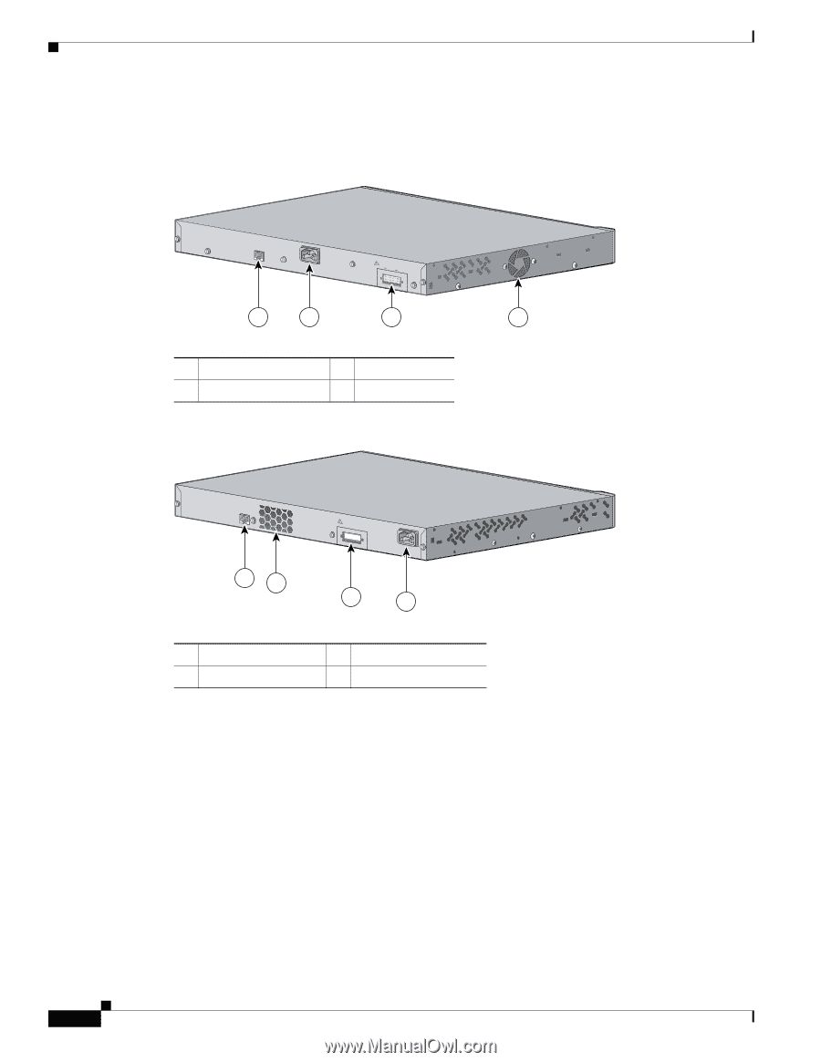
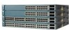
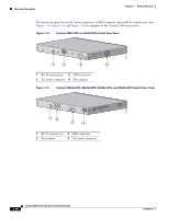
Rear Panel Description Chapter 1 Product Overview The switch rear panel has an AC power connector, an RPS connector, and an RJ-45 console port. (See Figure 1-14, Figure 1-15, and Figure 1-16 for examples of the Catalyst 3560 rear panels.) Figure 1-14 Catalyst 3560-24PS and 3560-48PS Switch Rear Panel CONSOLE 5.0A1-20R.05A-A2T,0IN500GV-6~0 HZ [email protected]@YMUO7A.TL8EA 97914 1 2 3 4 1 RJ-45 console port 3 RPS connector 2 AC power connector 4 Fan exhaust Figure 1-15 Catalyst 3560G-24PS, 3560G-48PS, 3560G-24TS, and 3560G-48TS Switch Rear Panel 119678 CONSOLE DSCPIENPCPOIUWFTIEESDRFISONURMPRPAELNYMUOATLE 12 3 4 1 RJ-45 console port 3 RPS connector 2 Fan exhaust 4 AC power connector 1-16 Catalyst 3560 Switch Hardware Installation Guide OL-6337-07
-
 1
1 -
2
-
3
-
4
-
5
-
6
-
7
-
8
-
9
-
10
-
11
-
12
-
13
-
14
-
15
-
16
-
17
-
18
-
19
-
20
-
 21
21 -
 22
22 -
 23
23 -
 24
24 -
 25
25 -
 26
26 -
 27
27 -
 28
28 -
 29
29 -
 30
30 -
 31
31 -
32
-
33
-
34
-
35
-
36
-
37
-
38
-
39
-
40
-
41
-
42
-
43
-
44
-
45
-
46
-
47
-
48
-
49
-
50
-
51
-
52
-
53
-
54
-
55
-
56
-
57
-
58
-
59
-
60
-
61
-
62
-
63
-
64
-
65
-
66
-
67
-
68
-
69
-
70
-
71
-
72
-
73
-
74
-
75
-
76
-
77
-
78
-
79
-
80
-
81
-
82
-
83
-
84
-
85
-
86
-
87
-
88
-
89
-
90
-
91
-
92
-
93
-
94
-
95
-
96
-
97
-
98
-
99
-
100
-
101
-
102
-
103
-
104
-
105
-
106
-
107
-
108
-
109
-
110
-
111
-
112
-
113
-
114
-
115
-
116
-
117
-
118
-
119
-
120
 |
 |