Cisco WS-C3560E-48PD-SF Hardware Installation Guide - Page 52
Connecting the Switch to Compatible Devices, Connecting to 10BASE-T or 100BASE-TX Devices
 |
View all Cisco WS-C3560E-48PD-SF manuals
Add to My Manuals
Save this manual to your list of manuals |
Page 52 highlights
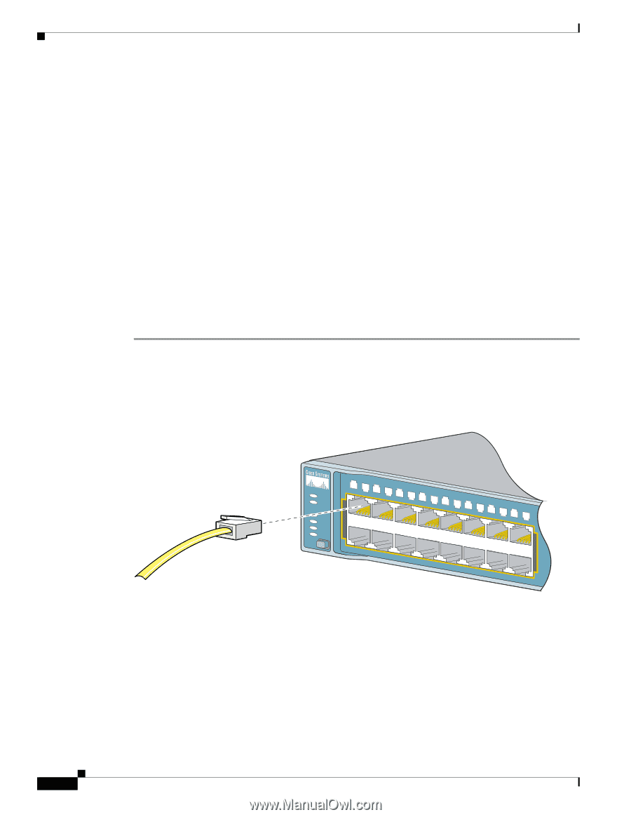
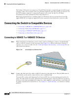
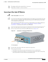
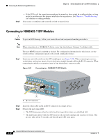
Connecting the Switch to Compatible Devices Chapter 2 Switch Installation (24- and 48-Port Switches) The Catalyst 3560 switch can connect to a Cisco IP Phone through a straight-through, twisted four-pair Category 5 cable. The rear panel of the Cisco IP Phone might have more than one RJ-45 connector. Use the LAN-to-phone connector to connect the IP phone to the switch. See the Cisco IP Phone documentation for more information about connecting devices. Many legacy powered devices, including older Cisco IP phones and access points that do not fully support IEEE 802.3af, might not support PoE when connected to the switches by a crossover cable. Connecting the Switch to Compatible Devices • Connecting to 10BASE-T or 100BASE-TX Devices, page 2-20 • Connecting to Fiber-Optic SFP Modules, page 2-21 • Connecting to 1000BASE-T SFP Modules, page 2-22 • Connecting to a Dual-Purpose Port, page 2-23 Connecting to 10BASE-T or 100BASE-TX Devices Step 1 When connecting to workstations, servers, routers, and Cisco IP Phones, connect a straight-through cable to an RJ-45 connector on the front panel. (See Figure 2-18.) When connecting to switches or repeaters, use a crossover cable. (See the "Cable and Adapter Specifications" section on page B-4 for cable-pinout descriptions.) Figure 2-18 Connecting to an Ethernet Port SYST RPS STAT DUPLX SPEED PoE MODE 1 1X 23 45 67 8 9 10 11 12 13 14 15 16 15X 2X 16X 97930 Step 2 Connect the other end of the cable to an RJ-45 connector on the other device. The port LED turns on when both the switch and the connected device have established link. The port LED is amber while Spanning Tree Protocol (STP) discovers the topology and searches for loops. This takes about 30 seconds, and then the port LED turns green. If the port LED does not turn on, the device at the other end might not be turned on, or there might be a cable problem or a problem with the adapter installed in the attached device. See Chapter 4, "Troubleshooting," for solutions to cabling problems. 2-20 Catalyst 3560 Switch Hardware Installation Guide OL-6337-07
-
 1
1 -
2
-
3
-
4
-
5
-
6
-
7
-
8
-
9
-
10
-
11
-
12
-
13
-
14
-
15
-
16
-
17
-
18
-
19
-
20
-
21
-
22
-
23
-
24
-
25
-
26
-
27
-
28
-
29
-
30
-
31
-
32
-
33
-
34
-
35
-
36
-
37
-
38
-
39
-
40
-
41
-
42
-
43
-
44
-
45
-
46
-
 47
47 -
 48
48 -
 49
49 -
 50
50 -
 51
51 -
 52
52 -
 53
53 -
 54
54 -
 55
55 -
 56
56 -
 57
57 -
58
-
59
-
60
-
61
-
62
-
63
-
64
-
65
-
66
-
67
-
68
-
69
-
70
-
71
-
72
-
73
-
74
-
75
-
76
-
77
-
78
-
79
-
80
-
81
-
82
-
83
-
84
-
85
-
86
-
87
-
88
-
89
-
90
-
91
-
92
-
93
-
94
-
95
-
96
-
97
-
98
-
99
-
100
-
101
-
102
-
103
-
104
-
105
-
106
-
107
-
108
-
109
-
110
-
111
-
112
-
113
-
114
-
115
-
116
-
117
-
118
-
119
-
120
 |
 |