Cisco WS-X4516-10GE Hardware Maintenance Manual - Page 47
Fiber Distributed Data Interface Connections, Distance Limitations for FDDI Connections - phy
 |
UPC - 746320977867
View all Cisco WS-X4516-10GE manuals
Add to My Manuals
Save this manual to your list of manuals |
Page 47 highlights
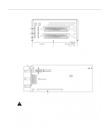
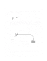
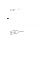
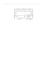
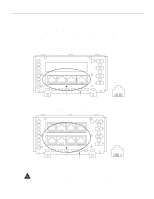
Network Connection Considerations Fiber Distributed Data Interface Connections Multimode FDDI network processor modules provide either a dual-attachment station (DAS) or a single-attachment station (SAS). Single-mode FDDI network processor modules provide a DAS. Following are the available FDDI module options: • Multimode dual-attachment • Multimode single-attachment • Single-mode dual-attachment The multimode FDDI network processor module consists of two cards, each with a multimode transceiver, with one card fitting on top of the other. The bottom card is the SAS and contains the PHY-A port. If the DAS option is included, the PHY-B port is located on the module's top card. Distance Limitations for FDDI Connections The distance limitations for single-mode and multimode FDDI stations are shown in Table 2-5. If the distance between two connected stations is greater than the maximum distance shown, significant signal loss can result. The single-mode transmitter and the multimode transceiver each provide 11 dB of optical power. Table 2-5 FDDI Maximum Transmission Distances Transceiver Type Maximum Distance Between Stations Single-mode Up to 6 miles (10 kilometers) Multimode Up to 1.2 miles (1.9 kilometers) FDDI Cable Connections The XMTR and RCVR ports of the single-mode network processor module (see Figure 2-24) use simplex FC-type connectors (see Figure 2-25). The ports accept standard 8.7 to 10/125-micron single-mode fiber-optic cable, supporting connections at distances up to 6 miles (10 kilometers). Figure 2-24 Dual-Attachment Single-Mode FDDI Module-End View PHY-B XMTR PHY-A RCVR FDDI WARNING PHY-B RING OP PHY-A RING OP AVOID EXPOSURE-INVISIBLE LASER RADIATION IS EMITTED FROM THESE APERTURES. 1300 NM CLASS 1 LASER PRODUCT LASERKLASSE 1 CISCO SYSTEMS, INC. 170 WEST TASMAN DRIVE SAN JOSE, CA 95134-1706 DATE: "Complies with FDA Radiation Performance Standards, 21 CFR, Subchapter J" Alignment groove Mounting screw locations Alignment groove H1614a Preparing for Installation 2-25
-
 1
1 -
2
-
3
-
4
-
5
-
6
-
7
-
8
-
9
-
10
-
11
-
12
-
13
-
14
-
15
-
16
-
17
-
18
-
19
-
20
-
21
-
22
-
23
-
24
-
25
-
26
-
27
-
28
-
29
-
30
-
31
-
32
-
33
-
34
-
35
-
36
-
37
-
38
-
39
-
40
-
41
-
 42
42 -
 43
43 -
 44
44 -
 45
45 -
 46
46 -
 47
47 -
 48
48 -
 49
49 -
 50
50 -
 51
51 -
 52
52 -
53
-
54
-
55
-
56
-
57
-
58
-
59
-
60
-
61
-
62
-
63
-
64
-
65
-
66
-
67
-
68
-
69
-
70
-
71
-
72
-
73
-
74
-
75
-
76
-
77
-
78
-
79
-
80
-
81
-
82
-
83
-
84
-
85
-
86
-
87
-
88
-
89
-
90
-
91
-
92
-
93
-
94
-
95
-
96
-
97
-
98
-
99
-
100
-
101
-
102
-
103
-
104
-
105
-
106
-
107
-
108
-
109
-
110
-
111
-
112
-
113
-
114
-
115
-
116
-
117
-
118
-
119
-
120
-
121
-
122
-
123
-
124
-
125
-
126
-
127
-
128
-
129
-
130
-
131
-
132
-
133
-
134
-
135
-
136
-
137
-
138
-
139
-
140
-
141
-
142
-
143
 |
 |
