Cobra 19 DX IV 19DXIV1 - Page 5
Operation - wiring
 |
View all Cobra 19 DX IV manuals
Add to My Manuals
Save this manual to your list of manuals |
Page 5 highlights
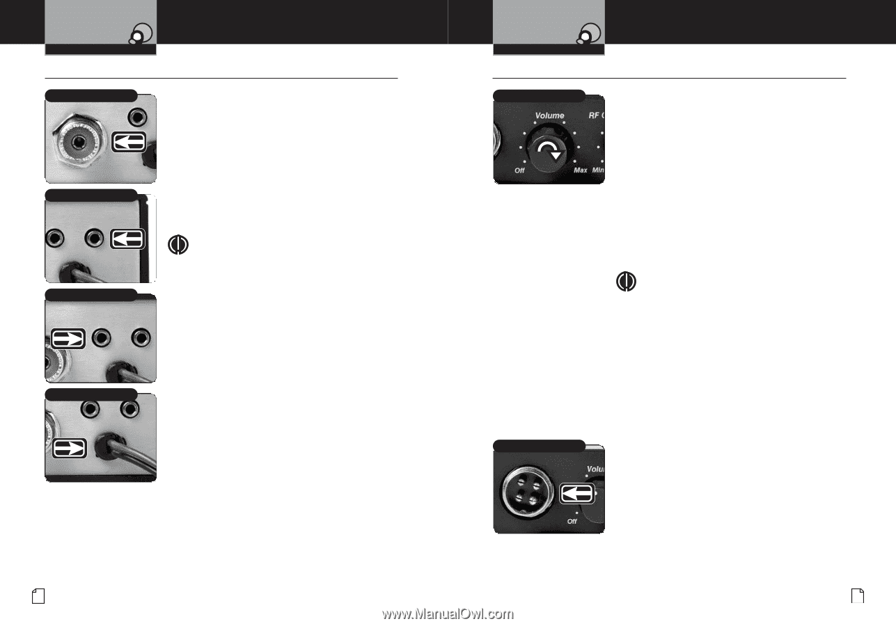
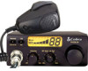
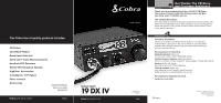
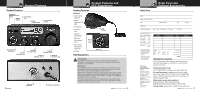
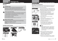
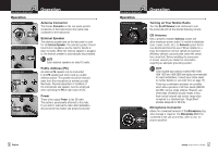
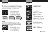
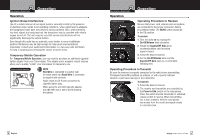
Assistance Customer Assistance Customer Assistance Customer Assistance Customer Caution Operation Main Icons Intro Operating Your Mobile Radio Operation Intro Operation Customer Warranty Operation Assistance • Operation Installation Antenna Connector Main Icons Installation Antenna Connector This female Connector on the rear panel permits Customer coAsnsinstaenccetion of the transmission line cable male Intro Secondary Icons Secondary Icons connector to the transceiver. Main Icons Intro External Speaker Operation Customer Assistance Warranty The external speaker jack on the rear panel is used Installation Notice External Speaker Jack for an External Speaker. The external speaker should Notice Caution Warning have 8-ohm impedance and be rated to handle at Installation Customer least 4.0Awssisatatntces. When the external speaker is plugged Secondary Icons Secondary Icons in, the internal speaker is automatically disconnected. Intro Operation Customer Warranty Assistance NOTE Main Icons Cobra external speakers are rated 15 watts. Notice Caution Warning Notice Installation PA Speaker Jack Secondary Icons Intro Operation Notice CustomPerublic Address (PA) An Assistance external PA speaker may be connected to the PA speaker jack when used as a public address system. The speaker should be directed Custoamweray fromWarrtahnety microphone to prevent acoustic Assistfaenceed-back. Physical separation or isolation of the microphone and speaker must be employed Cautwionhen opeWraarntiinngg the PA at high output levels. Power Cable Secondary Icons Installation Power Customer Assistance These wires supply Power to the CB radio. This cable is permanently attached to the radio. If you wish to remove the radio after installation, disconnect at fuse holder and ground connector. Notice Caution Warning Warranty Assistance Customer Assistance Customer Installation Operation Customer Assistance Operating Your Mobile Radio Secondary Icons Intro Operation Customer Warranty Operation Assistance • On-Off/Volume Knob Notice Turning on Your Mobile Radio Turn the On-Off/Volume knob clockwise to turn InstallaCtiaountion the power on CustomeWr arning Assistance and set the desired listening volume. Main Icons Secondary Icons CB Antenna Notice Intro Secondary Icons Only a properly matched Antenna system will allow maximum power output. In mobile installations (cars, trucks, boats, etc.), an Antenna system that is Caution Warning non-directional Operation Customer Assistance shoWaurraldnty be used. When installed in a boat, the transceiver will not operate at maximum efficiency without a ground plate unless the vessel has a Installation steCeusltohmeur ll. Before installing the transceiver in a boatA,sscisotanncesult your dealer for information regarding an adequate grounding system. Main Icons NOTE Cobra loaded-type antenna models HGA 1000, Notice HGACau1tio5n 00 anWdarnHingGA 2000 are highly recommended for most installations. Consult your Cobra dealer for further details (or see order form on page 17). Three-way combination antennas are available which allow operation of all three bands (AM-FM and CB), using a single antenna. However, use of this type of antenna usually results in less than normal transmit and receive range when compared to a standard-type "Single Band" antenna designed for CB only. Intro Operation Installation Microphone Connector Secondary Icons Microphone Connector Allows for convenient removal of the Microphone plug when storage is required. The Microphone MUST be connected to the unit at all times, when in use, for proper operation. Caution Notice Caution Warning 4 English Nothing comes close to a Cobra® 5
-
 1
1 -
 2
2 -
 3
3 -
 4
4 -
 5
5 -
 6
6 -
 7
7 -
 8
8 -
 9
9 -
 10
10 -
 11
11
 |
 |