Cobra 19 MINI AMFM 19 MINI Manual - English - Page 4
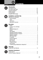
Installation and Start-Up, Included in this Package
 |
View all Cobra 19 MINI AMFM manuals
Add to My Manuals
Save this manual to your list of manuals |
Page 4 highlights
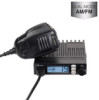
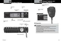
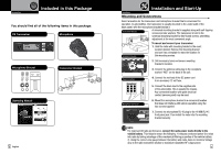
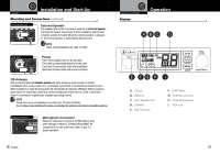
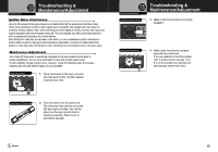
Operation Notice Caution Introduction Warning Included in this Package Intro Operation Customer Assistance Warranty You should find all of the following items in this package: Installation Customer Assistance CB TransceiverSecondary Icons Microphone Notice Caution Warning Microphone Bracket Transceiver Bracket Operating Manual 2 English Warning Warranty Warning Warranty Caution Assistance Customer Assistance Customer Caution Assistance Customer Assistance Customer Intro Operation Customer Assistance Warranty Installation and Start-Up Intsrtoadlluactitoionn Mounting and Connections Intro InstallatOiopneration CAsussitsotmanCAecsruessitsotmanecre Warranty • Select aSleococndaatryioIcnonsfor the transceiver and microphone bracket that is convenient for Main Icons operation. In automobiles, the transceiver is usually mounted to the underneath of the dash panel, with the micropInshtaollantieAonburnaivcekCArsuessstitsaotbmalneemcresoiduentiitn. g bracket is supplied along with self-tapping Transceiver Bracket Secondary Icons Notice scrCeawutiosnand staWrarwninagshers. The transceiver is held in the universal mounting bracket by two thumb screws, permitting adjustment at the most convenient angle. Intro Operation CB Tranceiver Installation Antenna Connector Main Icons Secondary Icons To mount and connect your transceiver: 1. Notice HoldCtahuteionradio wWitahrnimngounting bracket in the exact location desired. Remove the mounting bracket and use it as a template to mark the location for the mounting screws. 2. Drill necessary holes and secure mounting bracket in location. Operation Notice Fuse Connection Intro Main Icons Intro Secondary Icons 3. Connect the antenna cable plug to the receptacle marked "ANT" on the back of the unit. Operation Customer Assistance Warranty 4. Connect the red lead of the DC power cord to an accessory 12 volt fuse. 5. Connect the Installation Customer Assistance black lead to the negative side of the automobile. This is usually the chassis. Any convenient location with good electrical contact (remove paint) may be used. Installation Microphone Connector 6N.oticMe ount CthauetionmicropWhaorninnge bracket in a convenient location that does not interfere with vehicle operation using the two screws supplied. Secondary Icons 7. Connect the microphone RJ-45 plug to the 19 MINI RJ-45 front panel jack. Then install the radio into it's mounting bracket securely. Notice NOTE For improved CB radio performance, connect the radio power leads directly to the vehicle battery. This helps to ensure the following: 1) reduces conducted power line noise into radio by taking advantage of the mechanical filtering properties of the vehicle battery. 2) Using the correct wire gauge between the battery and radio, helps to minimize Voltage drop to the radio transmitter section to maximize transmitter RF output power. 3
-
 1
1 -
 2
2 -
 3
3 -
 4
4 -
 5
5 -
 6
6 -
 7
7 -
 8
8 -
 9
9 -
 10
10 -
11
 |
 |
