Cobra 19 MINI 19 MINI Manual - English - Page 5
Installation and Start-Up
 |
View all Cobra 19 MINI manuals
Add to My Manuals
Save this manual to your list of manuals |
Page 5 highlights
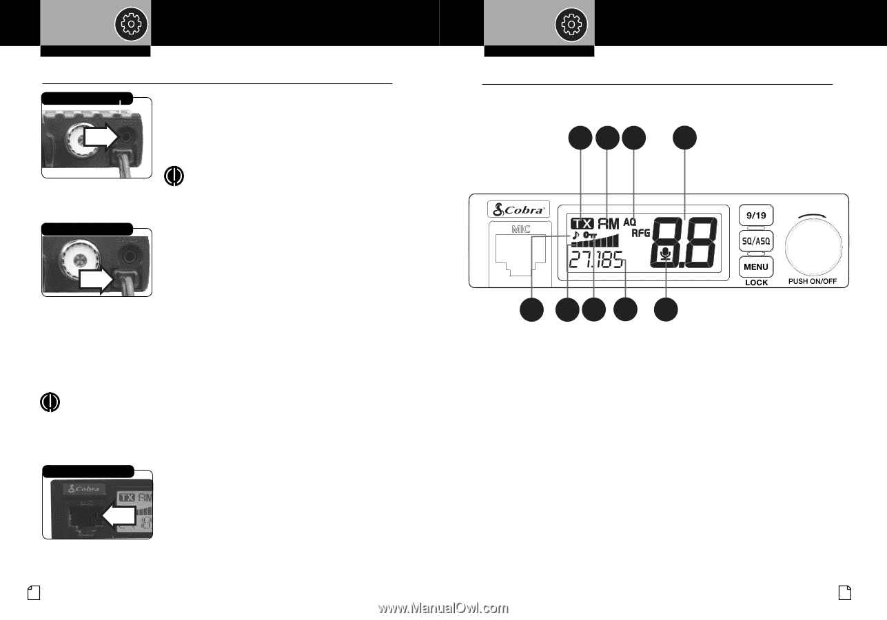
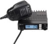
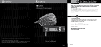
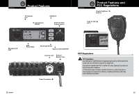
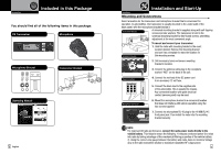
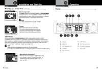
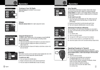
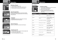
Main Icons Installation Installation and Start-Up Intro Operation Customer Warranty Mounting and ConnecAtssiisotannces continued • External Speaker Jack Secondary Icons Installation External Speaker TChuestosmpereaker jack on the rear panel is used for an External Speaker. TAhsesisetaxncteernal speaker should have 8-Ohm impedance and be rated to handle at least 4.0 watts. When the external speaker is plugged in, the internal speaker is automatically disconnected. NOTE Notice CautioCnobra exWtaernrinngal speakers are rated 15 watts. Power Cable InInstsatallallatiotionn Power These wires supply Power to the CB radio. This cable is permanently attached to the radio. If you wish to remove the radio after installation, disconnect at fuse holder and ground connector. CB Antenna Only a properly matched Antenna system will allow maximum power output. In mobile installations (cars, trucks, boats, etc.), an antenna system that is nondirectional should be used. When installed in a boat, the transceiver will not operate at maximum efficiency without a ground plate unless the vessel has a steel hull. Before installing the transceiver in a boat, consult your dealer for information regarding an adequate grounding system. NOTE Cobra offers a line of antennas for use with your 19 Series CB Radio. Go to cobra.com/collections/cb-radio-accessories for antenna and antenna mounting options. Microphone Connector Microphone Connector Allows for convenient removal of the Microphone plug when storage is required. The Microphone MUST be connected to the unit at all times, when in use, for proper operation. Main Icons Operating Your CB Radio Intro Display Operation Operation Customer Assistance Warranty Installation Customer Assistance Secondary Icons A BC D Notice Caution Warning • VOL E FG H I A. TX Icon B. AM Icon C. Auto Squelch Icon D. Channel E. Key Tone Icon F. S/RF Meter G. Channel Lock Icon H. Channel Frequency I. VOX Icon 4 English 5
-
 1
1 -
 2
2 -
 3
3 -
 4
4 -
 5
5 -
 6
6 -
 7
7 -
 8
8 -
 9
9 -
 10
10 -
 11
11
 |
 |