Compaq Evo n400c Compaq Evo Notebook N410c Series and N410c Series Maintenance - Page 115
Removing the Display, Remove the four TM2.0 × 6.0 screws
 |
View all Compaq Evo n400c manuals
Add to My Manuals
Save this manual to your list of manuals |
Page 115 highlights
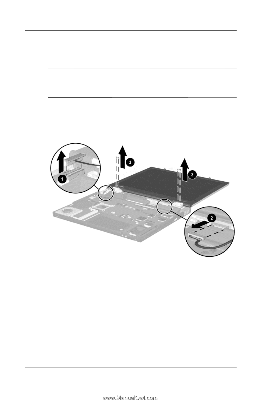
Removal and Replacement Procedures 2. Disconnect the display signal 1 and backlight 2 cables from the system board (Figure 5-23). ✎ When the display screws are removed, the display assembly is unsupported. Make sure to provide support for the display assembly when removing the display screws. 3. Remove the four TM2.0 × 6.0 screws 3 that secure the display to the base enclosure. 4. Remove the display. Figure 5-23. Removing the Display 5-30 Maintenance and Service Guide
-
 1
1 -
2
-
3
-
4
-
5
-
6
-
7
-
8
-
9
-
10
-
11
-
12
-
13
-
14
-
15
-
16
-
17
-
18
-
19
-
20
-
21
-
22
-
23
-
24
-
25
-
26
-
27
-
28
-
29
-
30
-
31
-
32
-
33
-
34
-
35
-
36
-
37
-
38
-
39
-
40
-
41
-
42
-
43
-
44
-
45
-
46
-
47
-
48
-
49
-
50
-
51
-
52
-
53
-
54
-
55
-
56
-
57
-
58
-
59
-
60
-
61
-
62
-
63
-
64
-
65
-
66
-
67
-
68
-
69
-
70
-
71
-
72
-
73
-
74
-
75
-
76
-
77
-
78
-
79
-
80
-
81
-
82
-
83
-
84
-
85
-
86
-
87
-
88
-
89
-
90
-
91
-
92
-
93
-
94
-
95
-
96
-
97
-
98
-
99
-
100
-
101
-
102
-
103
-
104
-
105
-
106
-
107
-
108
-
109
-
 110
110 -
 111
111 -
 112
112 -
 113
113 -
 114
114 -
 115
115 -
 116
116 -
 117
117 -
 118
118 -
 119
119 -
 120
120 -
121
-
122
-
123
-
124
-
125
-
126
-
127
-
128
-
129
-
130
-
131
-
132
-
133
-
134
-
135
-
136
-
137
-
138
-
139
-
140
-
141
-
142
-
143
-
144
-
145
-
146
-
147
-
148
-
149
-
150
-
151
-
152
-
153
-
154
-
155
-
156
-
157
-
158
-
159
-
160
-
161
-
162
-
163
-
164
-
165
-
166
-
167
-
168
-
169
-
170
-
171
-
172
 |
 |
5–30
Maintenance and Service Guide
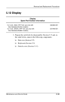
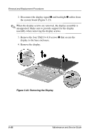
Removal and Replacement Procedures
2.
Disconnect the display signal
1
and backlight
2
cables from
the system board (Figure 5-23).
✎
When the display screws are removed, the display assembly is
unsupported. Make sure to provide support for the display
assembly when removing the display screws.
3. Remove the four TM2.0 × 6.0 screws
3
that secure the
display to the base enclosure.
4. Remove the display.
Figure 5-23. Removing the Display