Compaq Presario CQ20-400 Compaq Presario CQ20 Notebook PC - Maintenance and Se - Page 67
to lift the left side of the system board, until it rests at an angle.
 |
View all Compaq Presario CQ20-400 manuals
Add to My Manuals
Save this manual to your list of manuals |
Page 67 highlights
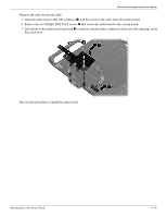
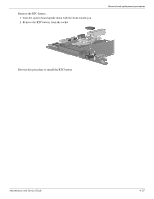
Removal and replacement procedures Remove the system board: 1. Remove the Torx T8M2.0×6.0 screw that secures the system board to the base enclosure. The screw is located beside the optical drive connector. 2. Flex the left side of the base enclosure until the USB jack, RJ-45 jack, and RJ-11 jack 1 clear the openings in the base enclosure. 3. Use the optical drive connector 2 to lift the left side of the system board 3 until it rests at an angle. 4. Remove the system board from the base enclosure by pulling it away at an angle 4. Reverse this procedure to install the system board. Maintenance and Service Guide 4-35
-
 1
1 -
2
-
3
-
4
-
5
-
6
-
7
-
8
-
9
-
10
-
11
-
12
-
13
-
14
-
15
-
16
-
17
-
18
-
19
-
20
-
21
-
22
-
23
-
24
-
25
-
26
-
27
-
28
-
29
-
30
-
31
-
32
-
33
-
34
-
35
-
36
-
37
-
38
-
39
-
40
-
41
-
42
-
43
-
44
-
45
-
46
-
47
-
48
-
49
-
50
-
51
-
52
-
53
-
54
-
55
-
56
-
57
-
58
-
59
-
60
-
61
-
 62
62 -
 63
63 -
 64
64 -
 65
65 -
 66
66 -
 67
67 -
 68
68 -
 69
69 -
 70
70 -
 71
71 -
 72
72 -
73
-
74
-
75
-
76
-
77
-
78
-
79
-
80
-
81
-
82
-
83
-
84
-
85
-
86
-
87
-
88
-
89
-
90
-
91
-
92
-
93
-
94
-
95
-
96
-
97
-
98
-
99
-
100
-
101
-
102
-
103
-
104
-
105
-
106
-
107
-
108
-
109
-
110
-
111
-
112
-
113
-
114
-
115
-
116
-
117
-
118
-
119
-
120
-
121
-
122
-
123
-
124
-
125
-
126
-
127
-
128
-
129
-
130
-
131
 |
 |
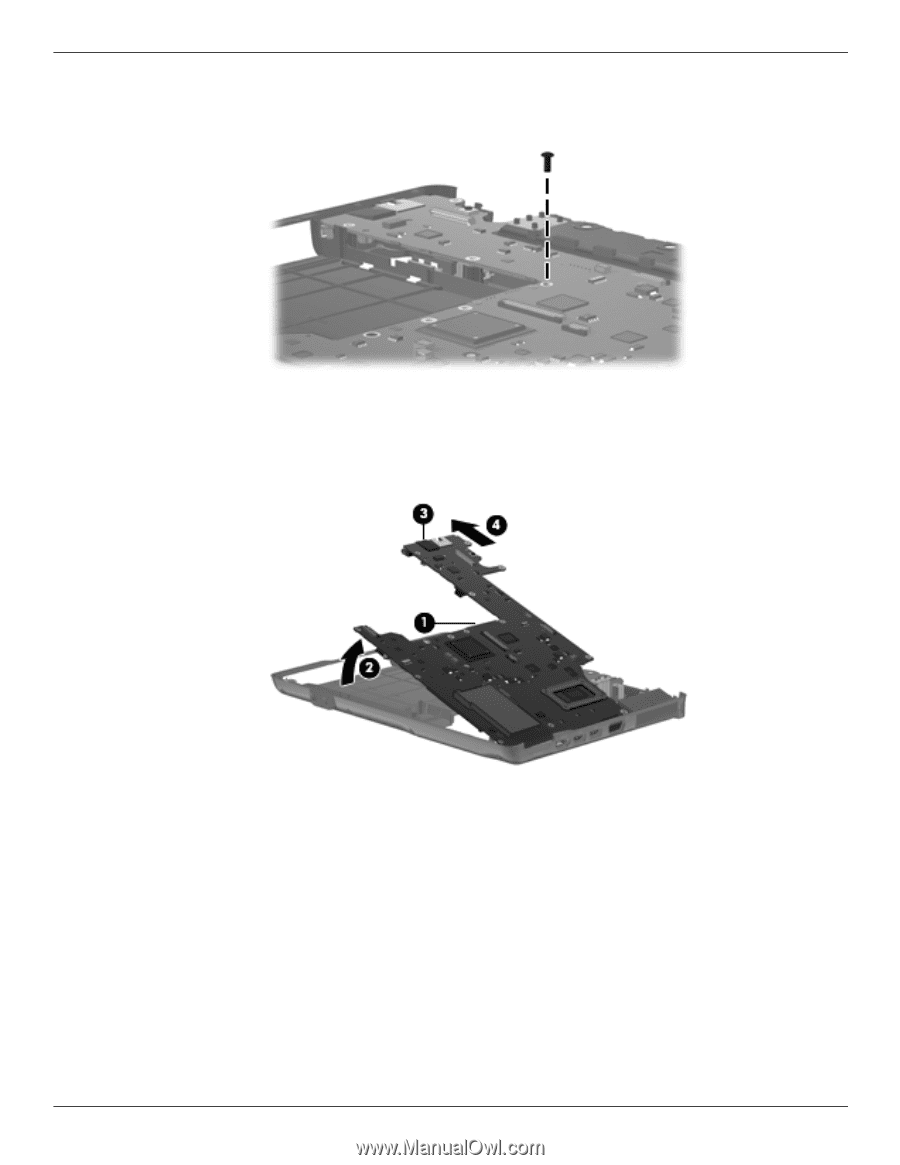
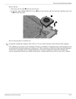
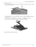
Removal and replacement procedures
Maintenance and Service Guide
4–35
Remove the system board:
1. Remove the Torx T8M2.0×6.0 screw that secures the system board to the base enclosure. The screw is located
beside the optical drive connector.
2. Flex the left side of the base enclosure until the USB jack, RJ-45 jack, and RJ-11 jack
1
clear the openings in
the base enclosure.
3. Use the optical drive connector
2
to lift the left side of the system board
3
until it rests at an angle.
4. Remove the system board from the base enclosure by pulling it away at an angle
4
.
Reverse this procedure to install the system board.