Compaq Presario CQ42-400 Compaq Presario CQ42 Notebook PC and HP G42 Notebook - Page 86
Display assembly, Remove the following components
 |
View all Compaq Presario CQ42-400 manuals
Add to My Manuals
Save this manual to your list of manuals |
Page 86 highlights
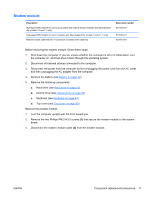
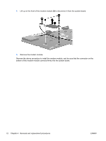
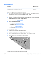
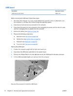
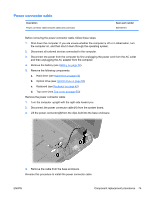
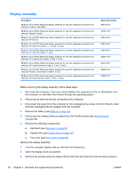
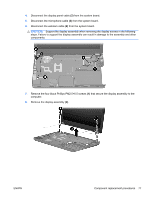
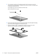
Display assembly Description 35.6 cm (14-in) WXGA Brightview display assembly for use with integrated microphone and webcam; Presario, matte black 35.6 cm (14-in) WXGA Brightview display assembly for use with integrated microphone and webcam; Presario, biscotti 35.6 cm (14-in) WXGA Brightview display assembly for use with integrated microphone and webcam; HP, biscotti 35.6 cm (14-in) WXGA Brightview display assembly for use with integrated microphone and webcam; HP, silver (for models 1.1, 1.2 and 1.3 only) 35.6 cm (14-in) WXGA Brightview display assembly for use with integrated microphone and webcam; HP, white (for model 1.1 only) 35.6 cm (14-in) WXGA Brightview display assembly for use with integrated microphone and webcam; HP, charcoal (for models 1.2 and 1.3 only) 35.6 cm (14-in) WXGA Brightview display assembly for use with integrated microphone and webcam; HP, imperial blue (for models 1.2 and 1.3 only) 35.6 cm (14-in) WXGA Brightview display assembly for use with integrated microphone and webcam; Presario, velvet red (for model 1.2 only) 35.6 cm (14-in) WXGA Brightview display assembly for use with integrated microphone and webcam; HP, velvet red (for models 1.2 and 1.3 only) Spare part number 592146-001 597617-001 600163-001 606155-001 606156-001 622571-001 622572-001 624966-001 630907-001 Before removing the display assembly, follow these steps: 1. Shut down the computer. If you are unsure whether the computer is off or in Hibernation, turn the computer on, and then shut it down through the operating system. 2. Disconnect all external devices connected to the computer. 3. Disconnect the power from the computer by first unplugging the power cord from the AC outlet and then unplugging the AC adapter from the computer. 4. Remove the battery (see Battery on page 52). 5. Disconnect the wireless antenna cables from the WLAN module (see WLAN module on page 58). 6. Remove the following components: a. Keyboard (see Keyboard on page 63) b. Optical drive (see Optical drive on page 56) c. Top cover (see Top cover on page 65) Remove the display assembly: 1. Turn the computer display-side up, with the front toward you. 2. Open the display as far as possible. 3. Remove the wireless antenna cables (1) from the hole and clips built into the base enclosure. 76 Chapter 4 Removal and replacement procedures ENWW
-
 1
1 -
2
-
3
-
4
-
5
-
6
-
7
-
8
-
9
-
10
-
11
-
12
-
13
-
14
-
15
-
16
-
17
-
18
-
19
-
20
-
21
-
22
-
23
-
24
-
25
-
26
-
27
-
28
-
29
-
30
-
31
-
32
-
33
-
34
-
35
-
36
-
37
-
38
-
39
-
40
-
41
-
42
-
43
-
44
-
45
-
46
-
47
-
48
-
49
-
50
-
51
-
52
-
53
-
54
-
55
-
56
-
57
-
58
-
59
-
60
-
61
-
62
-
63
-
64
-
65
-
66
-
67
-
68
-
69
-
70
-
71
-
72
-
73
-
74
-
75
-
76
-
77
-
78
-
79
-
80
-
 81
81 -
 82
82 -
 83
83 -
 84
84 -
 85
85 -
 86
86 -
 87
87 -
 88
88 -
 89
89 -
 90
90 -
 91
91 -
92
-
93
-
94
-
95
-
96
-
97
-
98
-
99
-
100
-
101
-
102
-
103
-
104
-
105
-
106
-
107
-
108
-
109
-
110
-
111
-
112
-
113
-
114
-
115
-
116
-
117
-
118
-
119
-
120
-
121
-
122
-
123
-
124
-
125
-
126
-
127
-
128
-
129
-
130
-
131
-
132
-
133
-
134
-
135
-
136
-
137
-
138
-
139
-
140
-
141
-
142
-
143
-
144
-
145
-
146
-
147
-
148
-
149
-
150
-
151
-
152
 |
 |