Compaq ProLiant 3000 PCI Bus Numbering in a Microsoft Windows NT Environment - Page 28
Reviewing the Test 2 Configuration – Addition of Two Controllers, Comparison of Test 1 to Test 2 -
 |
View all Compaq ProLiant 3000 manuals
Add to My Manuals
Save this manual to your list of manuals |
Page 28 highlights
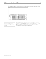
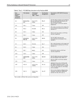
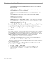
PCI Bus Numbering in a Microsoft Windows NT Environment 28 Reviewing the Test 2 Configuration - Addition of Two Controllers Configuration B−Test 2, illustrated in Table 9, provides an example of how the PCI BIOS discovers new controller devices not present in the original Test 1 configuration and how it assigns bus numbers during the discovery process. As in Test 1, the PCI BIOS moves through the bus detection order looking for controller devices (not slot numbers). In this example, the PCI BIOS begins at the Host Bus and assigns bus 0 to the Primary Bus. The PCI BIOS continues to search for the next device downstream on the Primary Bus. One bridged controller was added to the configuration on the Primary Bus. Upon discovery of each controller, the PCI BIOS assigns a bus number to the PCI bus on the bridged controller. Slot 2 now contains a NC3131 Fast Ethernet NIC on bus 1. Since slot 2 contained the last PCI device on the Primary Bus, the discovery process continues to the Secondary Bus. The Secondary Bus is assigned a bus number of 6. The NC3131 Fast Ethernet NIC in slot 5, a bridged device, is discovered next. The PCI BIOS assigns bus 7 to the PCI bus on the controller, the last PCI controller discovered on the Secondary Bus. The Tertiary Bus is assigned bus 13. The controllers downstream on the Tertiary Bus in slots 10 and 11 both contain bridges. Bus number assignments are made to the PCI buses on these bridged controllers. The Smart Array 4250ES Controller in slot 10 is assigned bus 14 and the Smart Array 4250ES Controller in slot 11 incremented to bus 15. Empty slots are ignored, because they do not contain PCI devices. Comparison of Test 1 to Test 2 - Configuration B When you reboot the server and run the System Configuration utility to view the hardware configuration changes, it displays slot and bus number assignments. Test 2 data was recorded and compared to Test 1. A side-by-side comparison of the slot configurations and bus numbers of each device in Test 1 to the slot configurations and bus numbers of each device in Test 2, illustrates what bus numbers were changed after modifications took place. Slot Controller Test 1 Test 2 Bus Assignment Slot 1 Empty N/A Slot 2 NC3131 (bridged) $ Bus 1 - New Slot 3 Empty N/A Slot 4 Empty N/A Slot 5 NC3131 (bridged) $ $ Bus 7 - No Change Slot 9 Empty N/A Slot 7 Empty N/A Slot 9 Empty N/A Slot 9 Empty N/A Slot 10 Smart Array 4250ES (bridged) $ Bus 14 - New Slot 10 Smart Array 4250ES (bridged) $ $ Bus 14 to 15 - Changed 13UK-1200A-WWEN
-
 1
1 -
2
-
3
-
4
-
5
-
6
-
7
-
8
-
9
-
10
-
11
-
12
-
13
-
14
-
15
-
16
-
17
-
18
-
19
-
20
-
21
-
22
-
 23
23 -
 24
24 -
 25
25 -
 26
26 -
 27
27 -
 28
28 -
 29
29 -
 30
30 -
 31
31 -
 32
32 -
 33
33 -
34
-
35
-
36
-
37
-
38
-
39
-
40
-
41
-
42
-
43
-
44
-
45
-
46
-
47
-
48
-
49
-
50
-
51
-
52
 |
 |