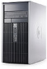
Compaq dc5850 Illustrated Parts & Service Map: HP Compaq dc5850 Microtower - Page 3
Setup Utility, Boot Block Emergency Recovery Mode, Password Security, Clearing CMOS - beep codes
 |
View all Compaq dc5850 manuals
Add to My Manuals
Save this manual to your list of manuals |
Page 3 highlights
Setup Utility Basic system information is maintained in the Setup Utility held in the system ROM, accessed by pressing the F10 key when prompted (on screen) during the boot sequence. Computer Setup Menu Heading Option/Description File System Information - Lists the following main system specifications: • Product name • SKU number (some models) • Processor type/speed/stepping • Cache Size (L1/L2) • Memory size/speed/ no. channels • Integrated MAC Address • System BIOS • Chassis serial number • Asset tracking number About - Displays copyright notice. Set Time and Date - Allows you to set system time and date. Flash System ROM - Allows you to select a drive containing a new BIOS. Replicated Setup-Save to Removable Media & Restore from Removable Media Default Setup • Save Current Settings as Default • Restore Factory Settings as Default Apply Defaults and Exit - Applies the selected default settings and clears any established passwords. Ignore Changes and Exit - Exits setup without applying or saving any changes. Save Changes and Exit - Saves changes to system configuration or default settings and exits Computer Setup. Storage Device Configuration - Lists all installed BIOS-controlled storage devices. The following options are available: • Diskette Type(Legacy Diskettes only)-3.5" 1.44 MB and 5.25" 1.2 MB • Emulation Type - ATAPI Zip drive, hard disk, legacy diskette, CD-ROM drive, and ATAPI LS-120 drive • Drive Emulation Type Options • Multisector Transfers • Translation Mode • Translation Parameters • Default Values SATA Storage Options: Removable Media Boot, Legacy Diskette Write, SATA Emulation, SATA 0 and 2, SATA 1 and 3 DPS Self-Test - Allows you to execute self-tests on ATA hard drives. Boot Order - Allows you to specify boot order. • Shortcut to Temporarily Override Boot Order Security Setup Password - Allows you to set and enable setup (Administrator) password. Power-On Password - Allows you to set and enable power-on password. Password Options - When any password exists allows you to lock legacy resources, enable/disable network server mode, specify password requirement for warm boot, and allows you to enable/disable Setup Browse Mode. Device Security (some models) - Enables/disables all I/O ports, audio, network controllers, SMBus controller, and embedded security devices. Network Service Boot - Enables/disables boot from OS on a server. System IDs - Allows you to set Asset tag, ownership tag, Chassis serial number, UUID, and keyboard locale setting. DriveLock Security-Lets you assign/modify hard drive p/w for added security. System Security (some models) - Allows you to enable/disable: • Data Execution Prevention • Virtualization Technology • Virtualization Technology Directed I/O • Trusted Execution Technology • Embedded Security Device Support • OS management of Embedded Security Device through OS • Virtual Appliance options • Smart Card BIOS Password Support Setup Security Level - Provides method to allow users limited access to change specified setup options without knowing Setup password. Power OS Power Management - Lets you enable/disable Runtime Power Management, Idle Power Savings, ACPI S3 Hard Disk Reset, ACPI S3 PS2 Mouse Wakeup, USB Wake on Device Insertion, Unique Sleep State Blink Rates. Hardware Power Management-Lets you enable/disable SATA bus power mgmt. Thermal - Allows you to control minimum permitted fan idle speed. Advanced Power-On Options - Allows you to set: • POST mode - QuickBoot, FullBoot, or FullBoot every 1-30 days. • POST messages - Enable/disable • MEBx Setup prompt - Enable/disable or hidden/displayed • F9 prompt - Enable/disable • F10 prompt - Enable/disable • F12 prompt - Enable/disable • Factory Recovery Boot Support - Enable/disable • Option ROM prompt - Enable/disable • WOL After Power Loss - Enable/disable • Remote wakeup boot source - Remote server/local hard drive • After Power Loss - Off/on/previous state • POST delay - None, 5, 10, 15, or 20 seconds • Limit CPUID Execute Memory Test -Restarts computer and executes POST memory test. BIOS Power-On - Allows you to set the computer to turn on at a preset time. Onboard Devices - Lets you set resources or disable onboard system devices. PCI Devices - Lists installed PCI devices with their IRQ settings and allows you to reconfigure IRQ or disable devices. PCI VGA Configuration - Allows you to specify which VGA controller will be used when multiple video adapters are available. Bus Options (some models) - Allows you to enable/disable PCI SERR# Generation and PCI VGA palette snooping. Device Options - Allows you to set: • Printer Mode - Bi-Directional, EPP & ECP, Output Only • Num Lock state at power-on - off/on • S5 Wake on LAN - enable/disable • Processor cache - enable/disable • Multi-Processor - enable/disable • Integrated video - enable/disable • Internal speaker - enable/disable • Monitor Tracking - enable/disable • NIC PXE Option ROM Download - enable/disable • SATA RAID Option ROM Download - enable/disable • HPET - enable/disable Boot Block Emergency Recovery Mode failure. For example, if a power failure were to occur during a BIOS upgrade, the ROM flash would be incomplete. This would render the system BIOS unusable. The Boot Block is a flashprotected section of the ROM that contains code that checks for a valid system BIOS image when the system is turned on. • If the system BIOS image is valid, the system starts normally. • If the system BIOS image is not valid, a failsafe Boot Block BIOS provides enough support to search removable media for BIOS image files. If an appropriate BIOS image file is found, it is automatically flashed into the ROM. When an invalid system BIOS image is detected, the system power LED will blink red 8 times, one blink every second. Simultaneously, the speaker will beep 8 times. If the portion of the system ROM containing the video option ROM image is not corrupt, Boot Block Emergency Recovery Mode will be displayed on the screen. To recover the system after it enters Boot Block Emergency Recovery Mode, complete the following steps: 1. Turn off the computer. 2. Insert a flash drive or CD containing the BIOS image in the root directory. The media must be formatted using the FAT12, FAT16, or FAT32 file system. 3. Turn on the computer. If no appropriate BIOS image is found, you will be prompted to insert media containing a BIOS image file. The system will automatically flash the ROM. After a successful flash, the system will either automatically restart or prompt the user to unplug the unit, wait 5 seconds, reattach the power cord, and then press the power button. 4. Remove the removable media used to upgrade the BIOS. 5. Turn the power on to restart the computer. NOTE: BitLocker prevents Windows Vista from booting when a CD containing the BIOS image file is in an optical drive. If BitLocker is enabled, remove this CD before attempting to boot to Windows Vista. Password Security Establishing a Setup password using computer setup 1. Turn on or restart the computer. If you are in Windows, click Start > Shut Down > Restart. 2. As soon as the computer is turned on, press F10 when the monitor light turns green to enter Computer Setup. Press Enter to bypass the title screen, if necessary. If you do not press F10 when prompted, a restart will be necessary. 3. Select Security > Setup Password and follow the instructions on the screen. 4. Before exiting, click File > Save Changes and Exit. Changing a Power-on or Setup password 1. Turn on or restart the computer. If you are in Windows, click Start > Shut Down > Restart. 2. If you want to change the Setup password, as soon as the computer is turned on, press F10 when the monitor light turns green to enter Computer Setup. Press Enter to bypass the title screen, if necessary. 3. If you want to change the Power-On password, when the key icon appears, type your current password, a slash (/) or alternate delimiter character, your new password, another slash (/) or alternate delimiter character, and your new password again as shown: current password/new password/new password. NOTE: Type the new password carefully since the characters do not appear on the screen. 4. Press Enter. The new password will take effect the next time the computer is restarted. Deleting a Power-on or Setup password 1. Turn on or restart the computer. If you are in Windows, click Start > Shut Down > Restart. 2. To delete the Setup password, as soon as the computer is turned on, press F10 when the monitor light turns green to enter Computer Setup. Press Enter to bypass the title screen, if necessary. 3. To delete the Power-on password, when the key icon appears, type the current password followed by a slash (/) or alternate delimiter character as shown: currentpassword/ 4. Press Enter. Clearing CMOS 1. Turn off the computer and any external devices, and disconnect the power cord from the power outlet. 2. Remove the access panel. 3. On the system board, press and hold the CMOS button for 5 seconds. 4. Replace the access panel, external devices, and reconnect the power cord. 5. Turn on the computer. You will receive POST error messages after clearing CMOS and rebooting advising you that configuration changes have occurred. Use Computer Setup to reset any special system setups along with the date and time. dc5850 Illustrated Parts & Service Map, MT 481406-001 page 3
-
 1
1 -
 2
2 -
 3
3 -
 4
4
 |
 |
