Compaq nx9000 Maintenance and Service Guide - Page 5
Tables, Example of Serial Number Label - bios
 |
View all Compaq nx9000 manuals
Add to My Manuals
Save this manual to your list of manuals |
Page 5 highlights
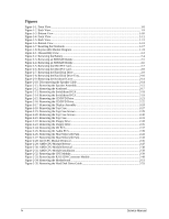
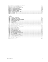
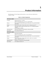
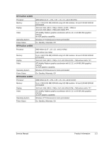
Figure 2-36. Disconnecting the Motherboard Cables 2-54 Figure 2-37. Removing the Motherboard 2-56 Figure 2-38. Example of Serial Number Label 2-59 Figure 2-39. Replacing the Antennas...2-60 Figure 2-37. Removing a PCMCIA Door 2-60 Figure 2-38. Boot-Block Jumper...2-62 Figure 3-1. Basic Troubleshooting Steps ...3-3 Figure 4-1. Exploded View ...4-2 Figure 4-2. Exploded View ...4-3 Tables Table 1-1. Product Comparisons...1-1 Table 1-2. Activating Power Modes ...1-14 Table 1-3. Main Status Lights (front of notebook 1-15 Table 1-4. Keyboard Status Lights...1-15 Table 1-5. Fn Hot Keys ...1-16 Table 1-6. Specifications...1-18 Table 1-7. Accessories ...1-22 Table 1-8. Functional Structure Description 1-25 Table 2-1. Removal Cross-Reference ...2-1 Table 2-2. Required Equipment ...2-2 Table 2-3. Recommended Screw Torque Values 2-2 Table 2-4. Replacing Small Parts ...2-12 Table 2-5. Removing Components...2-63 Table 3-1. ASP Support Options...3-2 Table 3-2. Scope of Diagnostic Tools...3-7 Table 3-3. Troubleshooting Suggestions...3-8 Table 3-4. POST Terminal-Error Beep Codes 3-20 Table 3-5. POST Messages ...3-24 Table 3-6. Sycard PCCtest Commands ...3-26 Table 3-7. BIOS Setup Menus and Parameters 3-28 Table 4-1. Replaceable Parts ...4-4 Table 4-2. Accessory Replaceable Parts 4-11 Table 4-3. Part Number Reference...4-12 Table 5-1. LCD Guidelines ...5-4 Service Manual v
-
 1
1 -
 2
2 -
 3
3 -
 4
4 -
 5
5 -
 6
6 -
 7
7 -
 8
8 -
 9
9 -
 10
10 -
 11
11 -
12
-
13
-
14
-
15
-
16
-
17
-
18
-
19
-
20
-
21
-
22
-
23
-
24
-
25
-
26
-
27
-
28
-
29
-
30
-
31
-
32
-
33
-
34
-
35
-
36
-
37
-
38
-
39
-
40
-
41
-
42
-
43
-
44
-
45
-
46
-
47
-
48
-
49
-
50
-
51
-
52
-
53
-
54
-
55
-
56
-
57
-
58
-
59
-
60
-
61
-
62
-
63
-
64
-
65
-
66
-
67
-
68
-
69
-
70
-
71
-
72
-
73
-
74
-
75
-
76
-
77
-
78
-
79
-
80
-
81
-
82
-
83
-
84
-
85
-
86
-
87
-
88
-
89
-
90
-
91
-
92
-
93
-
94
-
95
-
96
-
97
-
98
-
99
-
100
-
101
-
102
-
103
-
104
-
105
-
106
-
107
-
108
-
109
-
110
-
111
-
112
-
113
-
114
-
115
-
116
-
117
-
118
-
119
-
120
-
121
-
122
-
123
-
124
-
125
-
126
-
127
-
128
-
129
-
130
-
131
-
132
-
133
-
134
-
135
-
136
-
137
-
138
-
139
-
140
-
141
-
142
-
143
-
144
-
145
-
146
-
147
-
148
-
149
-
150
-
151
-
152
-
153
-
154
 |
 |