Corsair GS800 User Manual - Page 8
Installation - power supplie
 |
View all Corsair GS800 manuals
Add to My Manuals
Save this manual to your list of manuals |
Page 8 highlights
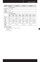
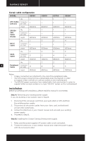
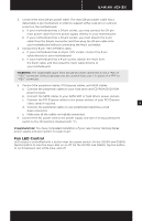
GAMING SERIES™ Corsair cable configuration MODEL GS500 GS600 GS700 GS800 Qty. 1 1 1 1 ATX Cable (24-pin) Connectors per Cable Length 1 600mm 1 600mm 1 600mm 1 600mm EPS12V CPU Cable (8-pin) Qty. Connectors per Cable Length 1 1 600mm 1 1 600mm 1 1 600mm 1 1 600mm Qty. 2 2 2 4 PCI-E Cable Connectors per Cable Length 1 600mm 1 600mm 1 600mm 1 600mm Qty. 2 2 2 2 SATA Cable Connectors per Cable Length 3 700mm 3 700mm 4 850mm 4 850mm Qty. 1 2 2 2 8 Peripheral Connectors Cable per Cable 4 4 4 5 Length 850mm 850mm 850mm 1000mm Notes: • Floppy connectors are attached to the end of the peripheral cable. • The ATX power connector has a detachable 4-pin mechanism in order to support either a 24-pin or a 20-pin socket on the motherboard. • The EPS12V power connector has a detachable 4-pin mechanism in order to support either an 8-pin socket or a 4-pin "P4/12V" socket on the motherboard. Installation Before proceeding with installation, please read this manual in its entirety. Step A: Removing your existing power supply If you are building a new system, skip to Step B. 1. Disconnect the AC power cord from your wall outlet or UPS and from the existing power supply. 2. Disconnect all the power cables from your video card, motherboard and all other peripherals. 3. Follow the directions in your chassis manual and uninstall your existing power supply. 4. Proceed to Step B. Step B: Installing the Corsair Gaming Series power supply 1. Make sure the power supply's AC power cable is not connected. 2. Follow the directions in your chassis manual and install the power supply with the screws provided.
-
 1
1 -
2
-
 3
3 -
 4
4 -
 5
5 -
 6
6 -
 7
7 -
 8
8 -
 9
9 -
 10
10 -
 11
11 -
 12
12 -
 13
13 -
14
-
15
-
16
-
17
-
18
-
19
-
20
-
21
-
22
-
23
-
24
-
25
-
26
-
27
-
28
-
29
-
30
-
31
-
32
-
33
-
34
-
35
-
36
-
37
-
38
-
39
-
40
-
41
-
42
-
43
-
44
-
45
-
46
-
47
-
48
-
49
-
50
-
51
-
52
-
53
-
54
-
55
-
56
-
57
-
58
-
59
-
60
 |
 |
