Craftsman 10137 Operation Manual - Page 12
Using
 |
UPC - 033287137145
View all Craftsman 10137 manuals
Add to My Manuals
Save this manual to your list of manuals |
Page 12 highlights
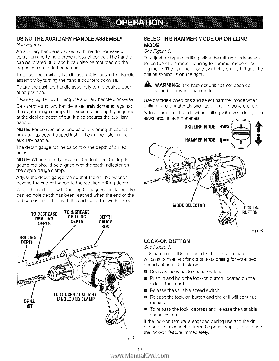
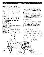
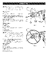
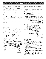
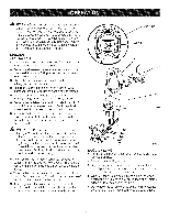
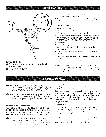
USINGTHE AUXILIARY HANDLE ASSEMBLY See Figure 5. An auxiliary handle is packed with the drill for ease of operation and to help prevent loss of control. The handle can be rotated 360 ° and it can also be mounted on the opposite side for left hand use. To adjust the auxiliary handle assembly, loosen the handle assembly by turning the handle counterclockwise. Rotate the auxiliary handle assembly to the desired operating position. Securely tighten by turning the auxiliary handle clockwise. Be sure the auxiliary handle is securely tightened against the depth gauge clamp. This secures the depth gauge rod at the desired depth of cut. It also secures the auxiliary handle. NOTE: For convenience and ease of staring threads, the hex nut has been trapped inside the molded slot in the auxiliary handle. The depth gauge rod helps control the depth of drilled holes. NOTE: When properly installed, the teeth on the depth gauge rod should be aligned with the teeth indicator on the depth gauge clamp. Adjust the depth gauge rod so that the drill bit extends beyond the end of the rod to the required drilling depth. When drilling holes with the depth gauge rod installed, the desired hole depth has been reached when the end of the rod comes in contact with the surface of the workpiece. TO DECREASE DRILLING TOINCREASE DRILLING DEPTH DEPTH DEPTH GAUGE ROD DRILL BIT TO LOOSENAUXILIARY HANDLEAND CLAMP Fig. 5 SELECTING HAMMER MODE OR DRILLING MODE See Figure 6. To adjust for type of drilling, slide the drilling mode selector on top of the motor housing to hammer mode or drilling mode. The hammer mode symbol is on the left and the drill bit symbol is on the right. _lb WARNING: The hammer drill has not been designed for reverse hammering. Use carbide-tipped bits and select hammer mode when drilling in hard materials such as brick, tile, concrete, etc. Select normal drill mode when drilling with twist drills, hole saws, etc., in soft materials. DRILLINGMODE _',m,',_ t HAMMER MODE Y MODESELECTOR LOCK-ON BUTTON Fig. 6 LOCK=ON BUTTON See Figure 6. This hammer drill is equipped with a lock-on feature, which is convenient for continuous drilling for extended periods of time. To lock-on: [] Depress the variable speed switch. [] Push in and hold the lock-on button, located on the side of the handle. [] Release the variable speed switch. [] Release the lock-on button and the drill will continue running. [] To release the lock, depress and release the variable speed switch. If the lock-on feature is engaged during use and the drill becomes disconnected from the power supply, disengage the lock-on feature immediately. 12
-
 1
1 -
2
-
3
-
4
-
5
-
6
-
 7
7 -
 8
8 -
 9
9 -
 10
10 -
 11
11 -
 12
12 -
 13
13 -
 14
14 -
 15
15 -
 16
16 -
 17
17 -
18
 |
 |