Craftsman 312HM Owners Manual - Page 2
Service Information Toll Free Number - receiver
 |
UPC - 753182407647
View all Craftsman 312HM manuals
Add to My Manuals
Save this manual to your list of manuals |
Page 2 highlights
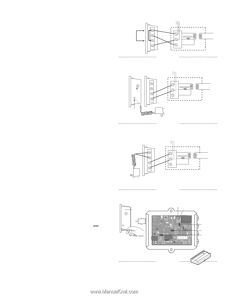
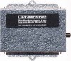
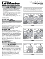
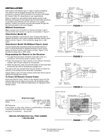
INSTALLATION The receiver and antenna use TV Type F coaxial connectors. The antenna can be plugged directly onto the receiver or mounted to a bracket and connected to the receiver with Model 86 Coaxial Cable Kit, depending on your requirements. Select a location for the receiver which allows access to the terminals and space for the antenna (as far from metal structures as possible and preferably with the antenna in an upright position). Fasten the receiver securely with screws through the two holes provided in the cover flanges. Without Transformer Make a jumper wire connection to receiver terminals 1 and 3. Connect wires from receiver to opener as illustrated in Figure 4. Transformer Model 85 Receiver terminals 1 and 2 are not used. Connect bell wire to receiver terminals 3 and 4 and to opener terminals used for push button controls. Figure 5. The transformer plugs into a 120V outlet. Transformer Model 95 (Without Plug-in Jack) Connect transformer secondary wires the receiver terminal 1 and 2. Connect bell wire to receiver terminals 3 and 4 and to opener terminals used for push button controls. Figure 6. The transformer plugs into a 120V outlet. Programming the Remote to the Receiver 1. Pry open the front panel of receiver case with a coin or a screwdriver. Re-connect power to opener. Figure 7. 2. Press and release the "learn" button on the receiver. The learn indicator light will glow steadily for 30 seconds. 3. Within 30 seconds, press and hold the button on the hand-held remote that you wish to operate your garage door. The opener will now operate when the push button on either the receiver or the remote control transmitter is pressed. Repeat Steps 2 and 3 for each remote control that will be used to operate the garage door opener. To Erase All Remote Control Codes Press and hold the "learn" button on the receiver panel until the indicator light turns off (about 6 seconds). All transmitter codes are now erased. Then follow the steps above to reprogram each remote control. SPECIFICATIONS Output Rating 5 Amps 28VAC or DC Max. Power 18V - 30V ~, 30mA, 60Hz 18 - 30V , 30mA RF Frequency 315MHz If the power is other than shown in specifications, Accessory Transformer Model 85 or 95 is required. Accessory Transmitters - Series 300. SERVICE INFORMATION TOLL FREE NUMBER 1-800-528-2806 CONNECT JUMPER WIRE TO TERMINALS 1 AND 3 RECEIVER WALL (Bottom) BUTTON 1 OPENER 2 1 Common 3 2 Relay 4 3 24 v TRANS PRIMARY FIGURE 4 RECEIVER RECEIVER WALL (Top) (Bottom) BUTTON 1 2 Connect Antenna 3 4 OPENER 1 Common 2 Relay 3 24 v Connect Transformer Model 85 Transformer To wall outlet FIGURE 5 TRANS PRIMARY RECEIVER WALL (Bottom) BUTTON OPENER 1 1 Common TRANS 2 2 PRIMARY Relay 3 3 4 24 v To wall Model 95 outlet Transformer FIGURE 6 OPENING RECEIVER Connect Antenna OPEN RECEIVER Indicator Light Learn Button C P2 M HIGH NORM 24V 12V Output Duration Terminals Security Mode Power Supply Jumper FIGURE 7 114A3097 © 2005, The Chamberlain Group, Inc. All Rights Reserved Printed in Mexico
-
 1
1 -
 2
2
 |
 |