Craftsman 74545 Operation Manual - Page 7
Top Black Collar - spool
 |
View all Craftsman 74545 manuals
Add to My Manuals
Save this manual to your list of manuals |
Page 7 highlights
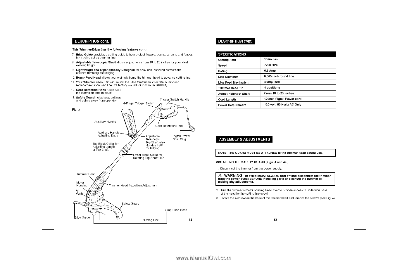
This Trimmer/Edger has the following features cont.: 7. Edge Guide provides a cutting guide to help protect flowers, plants, screens and fences from being cut by trimmer line. 8. Adjustable Telescopic Shaft allows adjustments from 16 to 25 inches for your ideal working height. 9. Lightweight and Ergonomicatly Designed for easy use, handling comfort and efficient trimming and edging. 10. Bump-Feed Head allows you to simply bump the trimmer head to advance cutting line. 11. Your Trimmer uses 0.065-in. round line. Use Craftsman 71-85967 bump feed replacement spool and line. it's factory wound for maximum reliability. 12, Cord Retention Hook helps keep the extension cord in place. 13, Safety Guard helps keep cuttings and debris away from operator, 4-Finger Trigger Switch Trigger Switch Handle Fig. 3 Auxiliary, Auxiliary Adjusting Knob Top Black Collar for Adjusting Length of Top Shaft Cord Retention Hook ustable Telescopic TRooptatSehsaft18a0ls°o for Edging Pigtail Power Cord Plug Rotating Top Shaft 180° Trimmer Head N Motor Housing Air Vents Edge Guide position Adjustment Safety Guard Bump-Feed Head Cutting Line 12 _ II:[_Ii[I@#Ii[s][i.I Cutting Path Speed Rating Line Diameter Line Feed Mechanism Trimmer Head Tilt Adjust Height of Shaft Cord Length Power Requirement 15 inches 7200 RPM 5.5 Amp 0.065 inch round line Bump feed 4 positions From 16 to 25 inches 12 inch Pigtail Power cord 120-volt, 60 Hertz AC Only I I NOTE: THE GUARD MUST BE ATTACHED to the trimmer head before use. I INSTALLING THE SAFETY GUARD (Figs. 4 and 4a ) 1. Disconnect the trimmer from the power supply. from the power outlet BEFORE installing parts or cleaning the trimmer or I m_akinWgARanNyINaGdju: stmTenotsa.void injury, ALWAYS turn off and disconnect the trimmer 2. Turn the trimmer's motor housing head over to provide access to underside base of the head by the cutting line spool. 3. Locate the 4 screws in the base of the trimmer head and remove the screws (see Fig. 4). 13
-
 1
1 -
 2
2 -
 3
3 -
 4
4 -
 5
5 -
 6
6 -
 7
7 -
 8
8 -
 9
9 -
 10
10 -
 11
11 -
 12
12 -
13
-
14
 |
 |