Cub Cadet GT 2050 Garden Tractor GT 2050 Operator's Manual - Page 27
Cutting Blades
 |
View all Cub Cadet GT 2050 Garden Tractor manuals
Add to My Manuals
Save this manual to your list of manuals |
Page 27 highlights
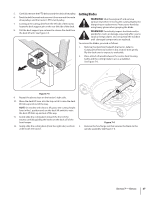
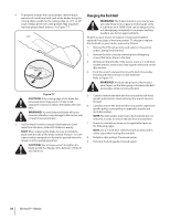
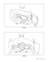
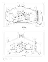
5. Carefully remove the PTO belt around the deck drive pulley, Cutting Blades 6. Feed the belt forward and remove it from around the mule drive pulleys and the tractor's PTO clutch pulley. 7. Looking at the cutting deck from the left side of the tractor, locate the deck support pin on the rear left side of the deck. WARNING! Shut the engine off and remove ignition key before removing the cutting blade(s) for sharpening or replacement. Protect your hands by using heavy gloves when grasping the blade 8. Pull the deck support pin outward to release the deck from the deck lift arm. See Figure 7-5. WARNING! Periodically inspect the blade and/or spindle for cracks or damage, especially after you've struck a foreign object. Do not operate the machine until damaged components are replaced. To remove the blades, proceed as follows. 1. Remove the deck from beneath the tractor, (refer to Cutting Deck Removal earlier in this section) then gently flip the deck over to expose its underside. 2. Place a block of wood between the center deck housing baffle and the cutting blade to act as a stabilizer. See Figure 7-6. Figure 7-5 9. Repeat the above steps on the tractor's right side. 10. Move the deck lift lever into the top notch to raise the deck lift links up and out of the way. NOTE: On models with electric lift, place the cutting height lever in the L position and use the deck lift switch to raise the deck lift links up and out of the way. 11. Gently slide the cutting deck toward the front of the tractor, carefully guiding the hooks on the deck off of the front hanger. 12. Gently slide the cutting deck (from the right side) out from 3. underneath the tractor. Figure 7-6 Remove the hex flange nut that secures the blade to the spindle assembly. See Figure 7-6. Section 7 - Service 27
-
 1
1 -
2
-
3
-
4
-
5
-
6
-
7
-
8
-
9
-
10
-
11
-
12
-
13
-
14
-
15
-
16
-
17
-
18
-
19
-
20
-
21
-
 22
22 -
 23
23 -
 24
24 -
 25
25 -
 26
26 -
 27
27 -
 28
28 -
 29
29 -
 30
30 -
 31
31 -
 32
32 -
33
-
34
-
35
-
36
-
37
-
38
-
39
-
40
 |
 |
