Cub Cadet PRO HW 348 Operation Manual - Page 7
Assembly & Set-Up
 |
View all Cub Cadet PRO HW 348 manuals
Add to My Manuals
Save this manual to your list of manuals |
Page 7 highlights
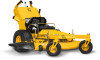
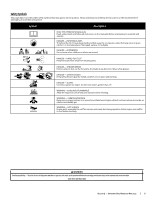
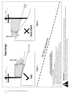
Assembly & Set-Up Thank You Thank you for purchasing this product. It was carefully engineered to provide excellent performance when properly operated and maintained. Please read this entire manual prior to operating the equipment. It instructs you how to safely and easily set up, operate and maintain your machine. Please be sure that you, and any other persons who will operate the machine, carefully follow the recommended safety practices at all times. Failure to do so could result in personal injury or property damage. All information in this manual is relative to the most recent product information available at the time. Review this manual frequently to familiarize yourself with the machine, its features and operation. Please be aware that this Operator's Manual may cover a range of product specifications for various models. Characteristics and features discussed and/or illustrated in this manual may 2 not be applicable to all models. We reserve the right to change product specifications, designs and equipment without notice and without incurring obligation. If applicable, the power testing information used to establish the power rating of the engine equipped on this machine can be found at www.opei.org or the engine manufacturer's web site. If you have any problems or questions concerning the machine, phone your local authorized service dealer or contact us directly. We want to ensure your complete satisfaction at all times. Throughout this manual, all references to right and left side of the machine are observed from the operating position. Contents of Carton • Mower (1) Mower Set-Up Discharge Chute Deflector (If Necessary) The discharge chute deflector must be installed before operating the riding mower. To install the discharge chute deflector, proceed as follows: 1. Remove the carriage screws (a) and flange lock nuts (b) installed on the mounting bracket (c) on the deck. See Figure 2-1. (d) (b) (b) (c) (a) (a) Figure 2-1 2. With the previously removed hardware (a & b), install the discharge chute deflector (d) on the deck as shown in Figure 2-1. Connecting the Battery Cables WARNING California PROPOSITION 65 Battery posts, terminals, and related accessories contain lead and lead compounds, chemicals known to the State of California to cause cancer and reproductive harm. Wash hands after handling. CAUTION When attaching battery cables, always connect the POSITIVE (Red) wire to its terminal first, followed by the NEGATIVE (Black) wire. For shipping reasons, both battery cables on your equipment may have been left disconnected from the terminals at the factory. To connect the battery cables, proceed as follows: • Mower Operators Manual (1) • Engine Operator's Manual (1) Note: The positive battery terminal is marked Pos. (+). The negative battery terminal is marked Neg. (-). 1. Remove the plastic cover, if present, from the positive battery terminal and attach the red cable to the positive battery terminal (+) with the bolt (a) and hex nut (b). See Figure 2-2. (b) (b) (a) (c) (a) Fuel & Oil 1. The fuel tank has a capacity of five gallons. Remove the fuel cap by turning it counterclockwise. Use only clean, fresh (no more than 30 days old), unleaded gasoline. Do not overfill the fuel tank. Fill the tank to the bottom of the filler neck, allowing some space in the tank for fuel expansion. WARNING Use extreme care when handling gasoline. Gasoline is extremely flammable and the vapors are explosive. Never fuel the machine indoors or while the engine is hot or running. Extinguish cigarettes, cigars, pipes and other sources of ignition. 2. Your mower is shipped with oil in the engine. However, you MUST check the oil level before operating. Refer to the Engine Operator's Manual for oil checking procedures. Figure 2-2 2. Remove the plastic cover, if present, from the negative battery terminal and attach the black cable to the negative battery terminal (-) with the bolt (a) and hex nut (b). See Figure 2-2. 3. Position the red rubber boot (c) over the positive battery terminal to help protect it from corrosion. Note: If the battery is put into service after the date shown on top/side of battery, charge the battery as instructed in the Product Care section on page 8 prior to operating the mower. WARNING Always check the engine oil level before each use as instructed in the Engine Operator's Manual. Add oil as necessary. Failure to do so may result in serious damage to your engine. Tire Pressure The recommended operating rear tire pressure is 14 psi. The caster wheels are semi-pneumatic and do not require air pressure. Check the tire pressure periodically and maintain equal pressure in both rear tires at all times. Important: Refer to the tire sidewall for exact tire manufacturer's recommended or maximum psi. Do not overinflate. Uneven tire pressure could cause the cutting deck to mow unevenly. 7
-
 1
1 -
 2
2 -
 3
3 -
 4
4 -
 5
5 -
 6
6 -
 7
7 -
 8
8 -
 9
9 -
 10
10 -
 11
11 -
 12
12 -
13
-
14
-
15
-
16
-
17
-
18
-
19
-
20
-
21
-
22
-
23
-
24
 |
 |
