Cub Cadet PRO Z 560S KW Owners Manual - Page 15
Lumbar Support Lever Not Shown, If
 |
View all Cub Cadet PRO Z 560S KW manuals
Add to My Manuals
Save this manual to your list of manuals |
Page 15 highlights
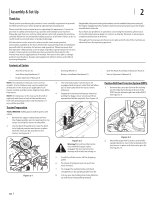
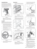
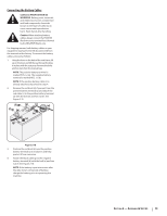
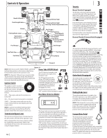
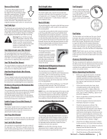
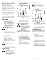
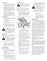
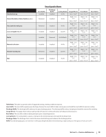
Reverse Drive Pedal The reverse drive pedal is located on the right side of the tractor, to the right of the forward drive pedal, along the running board. Ground speed is also controlled with the reverse drive pedal. The further downward the pedal is pivoted, the faster the tractor will travel. The pedal will return to its original/neutral position when it's not pressed. Fuel Tank Caps The fuel tank caps are located on the top of the fuel tank on the left and right side of the seat. Turn the fill cap counter-clockwise to remove and clockwise until it clicks three times to tighten. Always re-install the fuel cap tightly onto the fuel tank after removing. Warning! Never fill the fuel tank when the engine is running. If the engine is hot from recently running, allow to cool for several minutes before refueling. Highly flammable gasoline could splash onto the engine and cause a fire. Seat Adjustment Lever (Not Shown) The seat adjustment lever is located below the front/right of the seat. The lever allows for adjustment forward or rearward of the operator's seat. Refer to the Assembly & Set-Up section for instructions on adjusting the seat position. Seat Tilt Knob (Not Shown) The seat tilt knob is located on the left side of the seat. Refer to the Assembly & Set-Up section for instructions on adjusting the seat tilt. Arm Rest Height Knobs (Not Shown, If Equipped) The arm height knobs are located under the seat arms and can be used to adjust the height of the arm rests. Refer to the Assembly & Set-Up section for instructions on adjusting the arm rest position. Mechanical Suspension Mechanism (Not Shown, If Equipped) The mechanical suspension mechanism is located on the front of the seat and can adjust the weight/ ride adjustment for operators in the 125- to 275-pound weight range. Refer to the Assembly & Set-Up section for instructions on adjusting the mechanical suspension mechanism. Lumbar Support Lever (Not Shown, If Equipped) The lumbar support lever is located on the right side of the seat on the seat back. Refer to the Assembly & Set-Up section for instructions on adjusting the lumbar support. Seat Prop (Not Shown) The seat prop is located on the left, rear side of the operator's seat. It is used to prop the seat forward. Seat Latch (Not Shown) The seat latch is located below the rear, center of the operators seat. The latch is used to secure the seat into the operating position. Lift the latch and tilt the seat forward access the area under the seat. Deck Height Index Fuel Gauge(s) 4.25" 3.25" 2.25" 1.25" 4.50" 3.50" 2.50" 1.50" 4.75" 3.75" 2.75" 1.75" 5" 4" 3" 2" 1" The deck height index consists of several holes located on the left of the foot platform. Each hole corresponds to a 1⁄4" change in the deck height position ranging from 1" at the lowest notch to 5" at the highest notch. There is a fuel gauge on top of each of the two fuel tanks or a single gauge to the right of the operator's seat on the RH console. The gauges measure the fuel level in each tank. Deck Lift Pedal The deck lift pedal is located on the left front corner of the foot platform, and is used to raise and lower the mowing deck. To raise the mowing deck to the transport position, push the pedal all the way forward until the deck transportation lock snaps into position. To remove the deck from the transport position push forward on the deck lift pedal and pull up on the deck lock rod. To position the deck push the pedal all the way forward, remove the clevis pin and reinsert it in the desired cutting height and slowly release pressure on the pedal until you reach the clevis pin. Transport Lock The transport lock is located on the left side of the operator's seat and is used to lock the deck in the transport position. Press down on the deck lift pedal and lift up on the deck lift release lever to release the deck. TRANSPORT LOCK Transmission Oil Expansion Reservoir (Not Shown, If Equipped) The transmission oil expansion reservoir is connected by hoses to the RH and LH transmission assemblies, and is located under the seat. The function of the reservoir is to hold the natural expansion of transmission oil that occurs as the transmission warms up during operation. DO NOT FILL THE RESERVOIR. Under normal operating conditions, no oil should be added to the reservoir. The COLD oil level should be approximately 1⁄4" above the bottom of the reservoir. NOTE: Prior to the initial operation of the tractor, the oil level in the reservoir may be slightly higher than the maximum due to air in the oil lines. Operation of the tractor will eventually purge the air from the lines and the oil level will settle to the maximum. Steering Column Adjustment Lever The steering column adjustment lever is located on the right side of the steering column. To adjust the angle of the steering column rotate the lever counterclockwise, move the steering column to the desired position and then rotate the lever clockwise to lock it into position. NOTE: Be sure that the steering column adjustment lever is tight to prevent the column from moving when operating the tractor. Fuel Valves The fuel valves are located near the rear of each fuel tank. The valve controls the fuel flow from the right and left tank and also can shut off fuel flow to the engine. Rotate the valve clockwise to open the flow from the tank(s). Rotate the valve conterclockwise to stop the flow from the tank(s). The fuel tanks can be operated together, independantly or shut the fuel flow off completely. NOTE: IF both tanks are on, and one is empty the engine will not start. Be certain to make sure both tanks have fuel or that the empty tank's fuel valve is closed. Accessory Switch Receptacles The two receptacles for optional accessories are on the RH console. See the Attachments & Accessories section for information. The receptacles are for switches for an optional electric deck lift, lights and/or an auxiliary switch. Before Operating Your Machine 1. Before you operate the tractor, study this manual carefully to familiarize yourself with the operation of all the instruments and controls. It has been prepared to help you operate and maintain your machine efficiently. 2. Fill the fuel tank with only clean, fresh, unleaded gasoline with a pump sticker octane rating of 87 or higher. When the fuel reaches 1⁄2" below the bottom of the fill neck, stop. DO NOT OVERFILL. Space must be left for expansion. 3. Never use gasoline containing more than 10% ethanol or methanol. 4. Check the engine oil level as instructed in the Engine Operator's manual. 5. Check the transmission oil level. The transmission oil expansion reservoir is located beneath the operator's seat. Always wipe off the area around the reservoir fill neck before checking the oil level to prevent dirt from contaminating the oil. Remove the cap and make sure the oil level is a 1/4" above the bottom of the reservoir. If the oil level is low, fill with Castrol™ (Syntec®) Edge™. 6. Check the tire inflation pressures 10-12 psi for the rear tires, 20-25 psi for the front tires. NOTE: New tires are over-inflated in order to properly seat the bead to the rim. 7. Check that all nuts, bolts and screws are tight. 8. Check the tension of the deck drive belts. Section 3 - Controls & Operation 15
-
 1
1 -
2
-
3
-
4
-
5
-
6
-
7
-
8
-
9
-
 10
10 -
 11
11 -
 12
12 -
 13
13 -
 14
14 -
 15
15 -
 16
16 -
 17
17 -
 18
18 -
 19
19 -
 20
20 -
21
-
22
-
23
-
24
-
25
-
26
-
27
-
28
-
29
-
30
-
31
-
32
 |
 |