Cub Cadet SC 700 e Operation Manual - Page 9
Recoil Starter Rope Handle Assembly
 |
View all Cub Cadet SC 700 e manuals
Add to My Manuals
Save this manual to your list of manuals |
Page 9 highlights
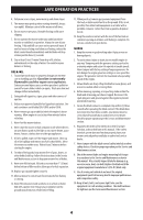
ASSEMBLY 4. Reattach knobs or wing nuts (a) and carriage bolts (b) removed in STEP 2 into lower holes of the handle or lock the EZ-fold handle release levers (c) (Figure 8). b a c Recoil Starter Rope Handle Assembly NOTE: The rope guide is attached to the right side of the upper handle. Loosen the knob securing the rope guide (Figure 10). 1. Hold blade control against upper handle. 2. Slowly pull recoil starter rope handle from engine and slip starter rope into the rope guide. 3. Tighten rope guide knob. 1 d Figure 8 IMPORTANT: When locking the EZ-fold handle release lever (c) ensure the position indicator (e) aligns with one of three handle positions (f) (Figure 9). e c f 2 3 Figure 10 NOTE: On select units, use the two cable clips provided to secure blade control and drive cables to lower handle (Figure 11). IMPORTANT: To reduce wear and allow for proper operation, make sure to leave some slack in the upper portion of the cables. Figure 9 5. Using the T-bolts (d) removed in STEP 2, secure the lower handle to the handle brackets (Figure 8) and tighten securely. Figure 11 9
-
 1
1 -
2
-
3
-
 4
4 -
 5
5 -
 6
6 -
 7
7 -
 8
8 -
 9
9 -
 10
10 -
 11
11 -
 12
12 -
 13
13 -
 14
14 -
15
-
16
-
17
-
18
-
19
-
20
-
21
-
22
-
23
-
24
-
25
-
26
-
27
-
28
-
29
-
30
-
31
-
32
-
33
-
34
-
35
-
36
-
37
-
38
-
39
-
40
-
41
-
42
-
43
-
44
-
45
-
46
-
47
-
48
-
49
-
50
-
51
-
52
-
53
-
54
-
55
-
56
-
57
-
58
-
59
-
60
-
61
-
62
-
63
-
64
 |
 |
