Cub Cadet Z-Force 54 Z-Force 48 Operator's Manual - Page 30
Battery Removal, Charging the Battery, Servicing Electrical System, Deck Removal
 |
View all Cub Cadet Z-Force 54 manuals
Add to My Manuals
Save this manual to your list of manuals |
Page 30 highlights
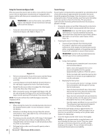
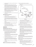
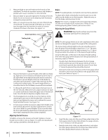
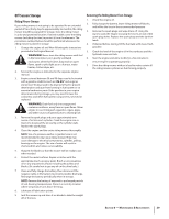
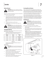
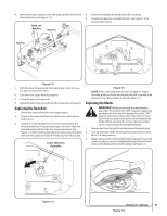
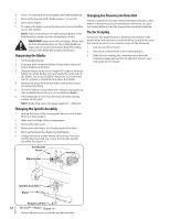
Service 7 Battery Removal WARNING! Battery posts, terminals and related accessories contain lead and lead compounds. Wash hands after handling. The battery is located on the right/rear of the tractor beneath the seat box frame. To remove the battery: 1. Remove the hold down straps. 2. Remove the hex cap screw and sems nut securing the black negative battery lead to the negative battery post (marked NEG). Move the cable away from the negative battery post. 3. Remove the hex cap screw and sems nut securing the red positive battery lead to the positive battery post (marked POS). 4. Carefully lift the battery out of the tractor. 5. Install the battery by repeating the above steps in the reverse order. WARNING! Always connect the positive lead to the battery before connecting the negative lead. This will prevent sparking or possible injury from an electrical short caused by contacting the tractor body with tools being used to connect the cables. Charging the Battery Test and, if necessary, recharge the battery after the tractor has been stored for a period of time. • A voltmeter or load tester should read 12.6 volts (DC) or higher across the battery terminals. See Figure 1-1. Voltmeter Reading 12.7 12.4 12.2 12.0 State of Charge 100% 75% 50% 25% Charging Time Full Charge 90 Min. 180 Min. 280 Min. Servicing Electrical System There is one fuse located in the wiring between the battery and ignition start switch. This is a standard plug-in type automotive fuse rated at 20 amp. Always use the same capacity fuse for replacement. If the electrical system does not function, check for a blown fuse. If you have a recurring problem with blown fuses, have the tractor's electrical system checked by your Cub Cadet Service Dealer. There are several safety switches in the electrical system (PTO Switch, PTO Clutch, Parking Brake/Drive Control Lever Switch, Seat Switch and No Cut in Reverse Switch). If a function of the safety interlock system described earlier is not functioning properly, have the electrical system checked by your Cub Cadet Service Dealer. Deck Removal WARNING! The muffler at the rear of the tractor may be extremely hot, and could cause serious burns. Use extreme caution when near the muffler. Allow the muffler to fully cool before removing the belt from the PTO pulley. Remove the mower deck from the tractor as follows: 1. Apply the parking brake. Remove ignition key and both spark plug caps. 2. Place the deck lift pedal in the lowest mowing position and replace the pin in front of pedal in the deck height bracket to secure it in place. NOTE: There is a certain amount of spring tension due to the weight of the deck. When removing the lift linkage from the deck the tension of the springs will go from the deck to the deck lift pedal. Not capturing the deck lift pedal while removing the lift linkage from the deck will cause it to snap back. 3. Reduce the tension on the PTO belt by moving the idler arm lever toward the back of the tractor, then remove the belt from the pulley. See Figure 1-2. Figure 1-1 • Charge the battery with a 12-volt battery charger at a MAXIMUM rate of 10 amps. Jump Starting WARNING!: Failure to use this starting procedure can cause sparking, and the gases in the battery to explode. Idler Arm Lever 1. Attach the end of the red jumper cable to the positive terminal (+) of the charged battery. 2. Attach the other end of the red jumper cable to the positive terminal (+) of the low charge battery. 3. Attach the end of the black jumper cable to the negative terminal of the charged battery. 4. Attach the other end of the black jumper cable to the frame of the unit with the low charge battery. Figure 1-2 30
-
 1
1 -
2
-
3
-
4
-
5
-
6
-
7
-
8
-
9
-
10
-
11
-
12
-
13
-
14
-
15
-
16
-
17
-
18
-
19
-
20
-
21
-
22
-
23
-
24
-
 25
25 -
 26
26 -
 27
27 -
 28
28 -
 29
29 -
 30
30 -
 31
31 -
 32
32 -
 33
33 -
 34
34 -
 35
35 -
36
-
37
-
38
-
39
-
40
 |
 |