CyberPower CP1000PFCLCD User Manual - Page 5
Basic Operation - function setup guide
 |
View all CyberPower CP1000PFCLCD manuals
Add to My Manuals
Save this manual to your list of manuals |
Page 5 highlights
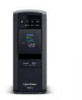
BASIC OPERATION 1. Power Switch Used as the master on/off switch for equipment connected to the battery power supplied outlets. 2. Power On Indicator This LED is illuminated when the utility power is normal and the UPS outlets are providing power, free of surges and spikes. 3. LCD module display High resolution and intelligent LCD display shows all the UPS information using icons and messages. For more information please review the "Definitions for Illuminated LCD Indicators" section below. 4. Down/Display Button The button can be used to select the LCD display contents including Input Voltage, Output Voltage, and Estimated Run Time. Short press the button to scroll down the function menu. Pressing the button for 2 seconds will keep the LCD display always on or turn the LCD display off while in AC/ Utility power mode. For more information about the Down/Display Button, please refer to the Function Setup Guide. 5. Up/Mute Button Short press the button to scroll up the function menu. Holding the button for more than 2 seconds will silence the alarm. For more information about the Up/Mute Button, please refer to the Function Setup Guide. 6. Enter/Setup Button Press the button for 2 seconds to enter the setup menu and then select the functions for configuration. For more information about the Enter/Setup Button, please refer to the Function Setup Guide. 7. USB charge ports (Except for CP850PFCLCD) The USB Power ports (Type A and Type C) provide DC 5V 3.1A power output with battery backup. 8. Battery and Surge Protected Outlets The unit has 5 battery powered and surge protected outlets to ensure temporary uninterrupted operation of your equipment during a power failure. (DO NOT plug a laser printer, paper shredder, copier, space heater, vacuum cleaner, sump pump, or other large electrical device into the "Battery and Surge Protected Outlets." The power demands of these devices will overload and possibly damage the unit.) 9. Full-Time Surge Protection Outlets The unit has 5 surge suppression outlets. 10. Circuit Breaker Located on the back of the UPS, the circuit breaker provides overload and fault protection. 11. Serial / USB Port to PC The port allows connection and communication between the Serial / USB port on the computer and the UPS unit. 12. Wiring Fault Indicator (red) This LED indicator will illuminate to warn the user that a wiring problem exists, such as bad ground, missing ground or reversed wiring. If this is illuminated, disconnect all electrical equipment from the outlet and have an electrician verify the outlet is properly wired. The unit will not provide surge protection without being plugged into a grounded and properly wired wall outlet. 13. Communication Protection Ports (RJ45) Bi-directional communication ports provide surge protection to a 10/100/1000 Ethernet connection.
-
 1
1 -
 2
2 -
 3
3 -
 4
4 -
 5
5 -
 6
6 -
 7
7 -
 8
8 -
 9
9 -
 10
10
 |
 |
