CyberPower CP1500PFCLCD User Manual - Page 8
Definitions For Illuminated Lcd Indicators, Troubleshooting
 |
View all CyberPower CP1500PFCLCD manuals
Add to My Manuals
Save this manual to your list of manuals |
Page 8 highlights
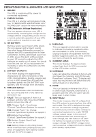
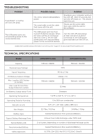
DEFINITIONS FOR ILLUMINATED LCD INDICATORS 13. OUTPUT meter: This meter measure, in real time, the AC voltage that the UPS system is providing to the computer, such as normal AC line mode, AVR mode, and battery backup mode. (Note: The OUTPUT meter shows the status of the battery backup outlets in terms of load, frequency, and voltage.) 14. EVENT: This meter records the number of power outages. 15. ESTIMATED RUNTIME: This displays the run time estimate of the UPS with current battery capacity and load. 16. SENSITIVITY setup: This meter is also used to setup the UPS sensitivity when you are in the programming mode. If the connected equipment can tolerate more power events (example: unstable power often associated with stormy weather), select Low Sensitivity and the UPS will go to Battery Mode less often. If the connected equipment is more sensitive to power events, select High Sensitivity and the UPS will go to Battery Mode more often. For more information about functions setup, please refer to the Function Setup Guide. TROUBLESHOOTING Problem Circuit breaker button is projecting from the back of the unit. The UPS does not perform expected runtime. The UPS will not turn on. PowerPanel® is inactive (all icons are gray). Possible Cause Solution Circuit breaker has been tripped due to an overload. Battery not fully charged. Battery is worn out. The on/off switch is designed to prevent damage from rapidly turning it off and on. The unit is not connected to an AC outlet. The battery is worn out. Mechanical problem. The USB cable is not connected. Turn the UPS off and unplug at least one piece of equipment. Wait 10 seconds, reset the circuit breaker by depressing the button, and then turn the UPS on. Recharge the battery by leaving the UPS plugged in. Contact CyberPower Systems about replacement batteries at: cyberpowersystems.com/support. Turn the UPS off. Wait 10 seconds and then turn the UPS on. The unit must be connected to a 110/120V 60Hz outlet. Contact CyberPower Systems about replacement batteries at: cyberpowersystems.com/support. Contact CyberPower Systems at: cyberpowersystems.com/support. Connect the USB / serial cable to the UPS unit and an open USB / serial port on the back of the computer. You must use the cable that came with the unit. The USB cable is connected to the wrong USB port. Check the back of the computer for an additional USB / serial port. Move the cable to this port.
-
 1
1 -
2
-
 3
3 -
 4
4 -
 5
5 -
 6
6 -
 7
7 -
 8
8 -
 9
9 -
 10
10
 |
 |