D-Link ANT70-1000 User Guide
D-Link ANT70-1000 - 8dBi/10dBi Dualband Indoor/Outdoor Antenna Manual
 |
UPC - 790069287213
View all D-Link ANT70-1000 manuals
Add to My Manuals
Save this manual to your list of manuals |
D-Link ANT70-1000 manual content summary:
- D-Link ANT70-1000 | User Guide - Page 1
DWL-AG700AP Install Guide User's Guide Version 2.02 ANT24-Series ANT70-Series D-Link Antenna Kits - D-Link ANT70-1000 | User Guide - Page 2
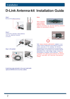
InSsystatelmlatRioenquirements ANT24-0700 Install Guide D-Link Antenna-kit Installation Guide Note: /antenna (If needed) Install the surge protector. (You can install with optional ANT24 series low loss cables) 2 - D-Link ANT70-1000 | User Guide - Page 3
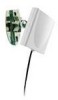
SysItnesmtaRlleaqtuioirnements D-Link Antenna-kit Installation Guide ANT24-SP Surge protector Installation guide for outdoor antenna-kit Step 1 loosen the screw from the surge protector. Option (1) Option (2) Step 2 get a normal conductive copper wire with 2 sides stripped long enough to be - D-Link ANT70-1000 | User Guide - Page 4
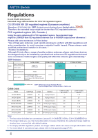
Based ANT24-0700 Install Guide Please add some sentences in P4 as below "Use of high gain antennas need careful planning to conform installer in all cases. " "Outdoor Installations Although D-Link offers a range of quality outdoor antennas, please note these devices are designed only to be - D-Link ANT70-1000 | User Guide - Page 5
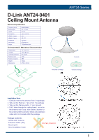
D-Link ANT24-0401 Ceiling Mount Antenna Electrical specification ASNysTte2m4-RSeeqruiieresments 58°~75° 110g without joint Environmental & Mechanical Characteristics Temperature -10°C to 55°C Humidity 100% @ 25 C Lightning protection DC ground Radome - D-Link ANT70-1000 | User Guide - Page 6
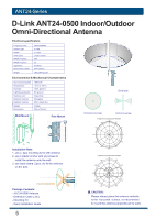
RSeeqruiieresments ANT24-0700 Install Guide D-Link ANT24-0500 Indoor/Outdoor Omni-Directional Antenna Omni-Directional Antenna Version 1 for com TEL: +886 (0)3 578-3188 FAX: +886 (0)3 578-3189 E-mail: [email protected] All right reserved by SmartAnt Telecom Co., Ltd. P1 EMW2403005AMLM01 6 - D-Link ANT70-1000 | User Guide - Page 7
ASNysTte2m4-RSeeqruiieresments D-Link ANT24-0501 Indoor Omni-Directional Antenna Electrical specification Frequency Range Impedance VSWR Return Loss Antenna Structure 2400~2500MHz 50Ω Normal 1.92 Max -10 dB Maximum Helis antenna Peak Gain ( w/o cable loss) Admitted Power Cable loss( 1.5m) E- - D-Link ANT70-1000 | User Guide - Page 8
-0700 Install Guide D-Link ANT24-0501C Indoor Omni-Directional Antenna Electrical specification Frequency Range Impedance VSWR ~ +75°C Color Antenna: Metallic gray and silver 36° Attach to AP/Router Package Contents -One ANT24-0501C 2.4GHz 5dBi indoor omni-directional antenna with a RP-SMA - D-Link ANT70-1000 | User Guide - Page 9
ASNysTte2m4-RSeeqruiieresments D-Link DWL-50AT Indoor Omni-Directional Antenna Electrical specification 5.0dBi Typical 2.0:1 Max. 360° 30 degree nominal 197 mm(length) 29.5gw 30° FFaarr--ffiieelldd aammpplliittuuddee ooff CC114477--551100001177--AA--VV..nnssii - D-Link ANT70-1000 | User Guide - Page 10
ASNysTte2m4-RSeeqruiieresments ANT24-0700 Install Guide D-Link DWL-R60AT Indoor Directional Antenna Electrical specification 6.0dBi Typical 2.0:1 Max. 70 85 nominal 80x85x12.8 mm 75gw 85° 10 - D-Link ANT70-1000 | User Guide - Page 11
-RSeeqruiieresments D-Link ANT24-0600 Indoor Directional Antenna Electrical specification Frequency Range Impedance VSWR Return Loss Antenna Structure Peak Gain ( w/o cable loss) Admitted Power Cable loss( 1.5m) E-Plane H-Plane 2400~2500MHz 50Ω Normal 1.92 Max -10 dB Maximum Pateh antenna 6.0 dBi - D-Link ANT70-1000 | User Guide - Page 12
-RSeeqruiieresments ANT24-0700 Install Guide D-Link ANT24-0700 Indoor Omni-Directional Antenna Electrical specification Frequency Range 2400~2500MHz Impedance 50Ω Normal VSWR Return Loss Antenna Structure Peak Gain ( w/o cable loss) 1.92 Max -10 dB Maximum Helis antenna 7dBi Admitted Power - D-Link ANT70-1000 | User Guide - Page 13
ASNysTte2m4-RSeeqruiieresments D-Link ANT24-0700C Indoor Omni-Directional Antenna Electrical specification Frequency Range Impedance VSWR Return Loss Antenna Structure 2400~2500MHz 50Ω Normal 1.92 Max 10 dB Maximum Helis antenna Peak Gain ( w/o cable loss) Admitted Power Cable loss( 1.5m) E- - D-Link ANT70-1000 | User Guide - Page 14
OASmNysTnte2im4-D-RSieerqeruiiecrestmioenntsal Antenna foArNT22.44-07G00HInzstall Guide ODAN-mTL2in4n-0ik-8D0A0iArN2eTct2i4o-n0a8l0A0nItnednonoar/Outdoor EElelcetcritcraicl aslpSecpieficciaftiicoantion Frequency range 2400 MHz - 2500 MHz Gain VSWR 8.0 dBi 2.0. : 1 Max. Polarization Linear, - D-Link ANT70-1000 | User Guide - Page 15
ASNysTte2m4-RSeeqruiieresments D-Link ANT24-0801 Indoor/Outdoor Directional Panel Antenna Electrical specification Frequency Gain VSWR Polarization HPBW / horizontal HPBW / vertical Front to back ratio 2400~2500MHz 8.5 dBi 1.5 : 1 Max Linear, vertical 65 65 15 dB - D-Link ANT70-1000 | User Guide - Page 16
ASNysTte2m4-RSeeqruiieresments ANT24-0700 Install Guide D-Link ANT24-1200 Indoor Directional Panel Antenna Electrical specification Frequency range Gain VSWR Polarization HPBW / horizontal HPBW / vertical Front to back ratio 2400 MHz - 2500 MHz 12 dBi 1.5 : 1 Max Linear, vertical 80 23 15 dB - D-Link ANT70-1000 | User Guide - Page 17
ASNysTte2m4-RSeeqruiieresments D-Link ANT24-1201 Outdoor Directional Yagi Antenna Electrical specification Frequency range 2400 MHz - 2500 MHz Gain 12 dBi VSWR 1.5 : 1 Max Polarization Linear, vertical HPBW / horizontal 50 50 HPBW / vertical 50 Front to back ratio 15 dB - D-Link ANT70-1000 | User Guide - Page 18
ASNysTte2m4-RSeeqruiieresments ANT24-0700 Install Guide D-Link ANT24-1400 Outdoor Directional Panel Antenna Electrical specification Frequency range Gain VSWR Polarization HPBW / horizontal HPBW / vertical Front to back ratio Downtilt 2400 MHz - 2500 MHz 14 dBi 1.5 : 1 Max Linear, vertical 30 30 - D-Link ANT70-1000 | User Guide - Page 19
ASNysTte2m4-RSeeqruiieresments D-Link ANT24-1400(cont.) Outdoor Directional Panel Antenna Pole mounting method 1. Pole mounting method 2. 19 - D-Link ANT70-1000 | User Guide - Page 20
ASNysTte2m4-RSeeqruiieresments ANT24-0700 Install Guide D-Link ANT24-1500 Outdoor OmniDirectional Panel Antenna Electrical specification Frequency Range Impedance SWR Gain Radiation 2400~2500 MHz 50 OHMS ±5Ω 1=1.3 Max 15 dBi Omni directional Polarization Vertical Mechanical Properties - D-Link ANT70-1000 | User Guide - Page 21
ASNysTte2m4-RSeeqruiieresments D-Link ANT24-1800 Outdoor Directional Panel Antenna Electrical specification Frequency range Gain VSWR Polarization HPBW / horizontal HPBW / vertical Front to back ratio 2400 MHz - 2500 MHz 18 dBi 1.5 : 1 Max Linear, vertical 15 15 26 dB Downtilt 0 - D-Link ANT70-1000 | User Guide - Page 22
ASNysTte2m4-RSeeqruiieresments ANT24-0700 Install Guide D-Link ANT24-1801 Outdoor Directional Panel Antenna Electrical specification Frequency range Gain VSWR Polarization HPBW / horizontal HPBW / vertical Front to back to +80 C 95% @ 25 C DC ground White ABS, UV resistant 3.5 kgw 1000 x 89 mm 22 - D-Link ANT70-1000 | User Guide - Page 23
GHz Antenna 12C.4OG-2H40z02Antenna ASNysTte2m4-RSeeqruiieresments EVERTIME Communications Co., Ltd. D-Link ANT24- TECHNICAL DATA TECHNICAL DATA Electrical Properties Electrical Properties Frequency Range : 2400~2485 MHz Frequency Range Impedance ʳʳʳʳʳISmWpRedance ʳʳʳSGWaiRn : : 2400~2485 50 - D-Link ANT70-1000 | User Guide - Page 24
ASNysTte7m0-RSeeqruiieresments ANT24-0700 Install Guide D-Link ANT70-0800 DuDal-uBaanld-OBmanni-DdirecOtiomnalnAin-teDnniraectional Antenna Electrical specification for 2.4 / 5.2 / 5.4 GHz Frequency Range 2400 MHz - 2500 MHz 4900 MHz - 5470 MHz Gain 8 dBi 8 dBi ANVTSW7R0-0800 2.0 : 1 Max. - D-Link ANT70-1000 | User Guide - Page 25
ASNysTte7m0-RSeeqruiieresments D-Link ANT70-0801 DDuaul-aBaln-dBOamnni-dDirOectmionnal iA-nDtenirnaectional Antenna fEolerctr2ic.a4l s/pe5ci.fi4ca/tio5n.6 / 5.8 GHz Frequency Range AGaNin T70-0801 2400 MHz - 2500 MHz 5400 MHz - 5875 MHz 8 dBi 8 dBi EVlSeWcRtrical Specificat2i.0o:n1 Max. HPBW - D-Link ANT70-1000 | User Guide - Page 26
ASNysTte7m0-RSeeqruiieresments ANT24-0700 Install Guide D-Link ANT70-1000 Dual-Band Directional Panel Antenna Electrical specification Frequency Range Gain VSWR HPBW / horizontal HPBW / vertical Polarization Power handling Front to back ratio Downtilt Impedance Connector 2400 MHz - 2500 MHz 4900 - D-Link ANT70-1000 | User Guide - Page 27
ASNysTte7m0-RSeeqruiieresments D-Link ANT70-1800 Dual-Band Directional Panel Antenna Electrical specification Frequency Range Gain VSWR HPBW : Package Contents -D-Link ANT70-1800 Antenna -Extension Cable(50cm) -Surge Protector -Mounting Kit -Water-proof tape -Quick Installation Guide 2.4 GHz: 5 - D-Link ANT70-1000 | User Guide - Page 28
Guide Line-of-Sight (LOS) Visual and RF Line-of-Sight ( LOS ) between the sending and receiving antennas is essential in achieving long range obstructed by the earth resulting in significant reduction in range. To avoid this problem, the antenna should be mounted high enough off of the ground so - D-Link ANT70-1000 | User Guide - Page 29
to or at least 70% of the radius of the Fresnel zone. Required Fresnel Zone radius Fresnel Zone Radius: Range Distance between Required Fresnel Zone Required Fresnel Zone antennas Radius ( 2.4GHz Radius) Radius ( 5GHz Radius) 300m 3.06m 2.12m 1.6Km 7.07m 4.9m 8Km 15.81m 10.95m 10Km 17 - D-Link ANT70-1000 | User Guide - Page 30
range Gain (Without cable loss) Approximate Range at 1 / 11/ 54Mbps ( Works with Indoor AP ) Approximate Range at 1/ 11 /54Mbps (Works with Outdoor AP) Half Power Beam width Pigtail cable length Antenna /magnetic Attach to AP/Router Wall/ desktop/magnetic Attach to AP/Router ANT24-SP --- --- - D-Link ANT70-1000 | User Guide - Page 31
Model Name Frequency Signal directivity Application range Gain (Without cable loss) Approximate Range at 1 / 11/ 54Mbps ( Works with Indoor AP ) Approximate Range at 1/ 11 /54Mbps (Works with Outdoor AP) Half Power Beam width Pigtail cable length Antenna fixed connector Surge protector for outdoors - D-Link ANT70-1000 | User Guide - Page 32
range Gain (Without cable loss) Approximate Range at 1 / 11/ 54Mbps ( Works with Indoor AP ) Approximate Range at 1/ 11 /54Mbps (Works with Outdoor AP) Half Power Beam width Pigtail cable length Antenna ANT24-CB series ANT24-ODU series ANT24-DLK series ANT24-0700 Install Guide System Requirements - D-Link ANT70-1000 | User Guide - Page 33
Model Name ANT70-0800 ANT70-0801 ANT70-1000 ANT70-1800 Frequency 2.4GHz/ 5GHz 2.4GHz/ 5GHz 2.4GHz/ 5GHz 2.4GHz/ 5GHz Signal directivity Omni-Directional Omni-Directional Directional Directional Application range Gain (Without cable loss) Approximate Range at 1 / 11/ 54Mbps ( Works - D-Link ANT70-1000 | User Guide - Page 34
System Requirements 34 (Appendix) CONNECTORS OUTLOOK Ϳ͑ΝΦΘ Ϳ͑ͻΒΔΜ Ϳ͑ͻΒΔΜ ANT24-0700 Install Guide
-
 1
1 -
 2
2 -
 3
3 -
 4
4 -
 5
5 -
 6
6 -
 7
7 -
8
-
9
-
10
-
11
-
12
-
13
-
14
-
15
-
16
-
17
-
18
-
19
-
20
-
21
-
22
-
23
-
24
-
25
-
26
-
27
-
28
-
29
-
30
-
31
-
32
-
33
-
34
 |
 |

DWL-AG700AP Install Guide
Version 2.02
ANT24-Series
ANT70-Series
D-Link Antenna Kits
User’s Guide