D-Link DES-1316 Product Manual - Page 12
Rack Mounting
 |
UPC - 790069271700
View all D-Link DES-1316 manuals
Add to My Manuals
Save this manual to your list of manuals |
Page 12 highlights
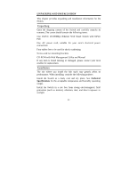
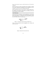
Leave at least 10cm of space at the front and rear of the hub for ventilation. Install the Switch on a sturdy, level surface that can support its weight, or in an EIA standard-size equipment rack. For information on rack installation, see the next section, titled Rack Mounting. When installing the Switch on a level surface, attach the rubber feet to the bottom of each device. The rubber feet cushion the hub and protect the hub case from scratching. Rack Mounting The Switch can be mounted in an EIA standard-size, 19-inch rack, which can be placed in a wiring closet with other equipment. Attach the mounting brackets at the Switch's front panel (one on each side), and secure them with the provided screws. Figure 1. Combine the Switch with the provided screws. Then, use screws provided with the equipment rack to mount each switch in the rack. Figure 2. Mount the Switch in the rack. 12
-
 1
1 -
2
-
3
-
4
-
5
-
6
-
 7
7 -
 8
8 -
 9
9 -
 10
10 -
 11
11 -
 12
12 -
 13
13 -
 14
14 -
 15
15 -
 16
16 -
 17
17 -
18
-
19
-
20
-
21
-
22
-
23
-
24
-
25
-
26
-
27
-
28
-
29
-
30
-
31
-
32
-
33
-
34
-
35
-
36
-
37
-
38
-
39
-
40
-
41
-
42
-
43
-
44
-
45
-
46
-
47
-
48
-
49
-
50
-
51
-
52
-
53
-
54
-
55
-
56
-
57
 |
 |
