D-Link DGS-1100-05 Manual - Page 8
Rear Panel, DGS-1100-16, Front Panel - 16 configuration
 |
View all D-Link DGS-1100-05 manuals
Add to My Manuals
Save this manual to your list of manuals |
Page 8 highlights
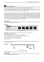
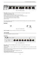
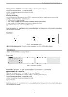
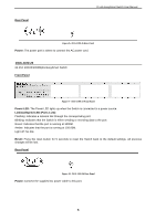
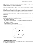
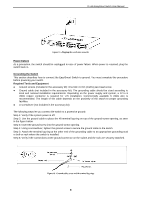
D-Link EasySmart Switch User Manual Blinking: Indicates that the Switch is either sending or receiving data to the port. Green: Indicates that the port is running at 1000M. Amber: Indicates that the port is running at 10/100M. Light off: No link. PoE LED (Ports 1-8): Green: Indicates the PoE powered device (PD) is connected and the port supplies power successfully. Red: The PoE port has failed, possibly due to: 1. PoE total power budget shortage 2. Over current: Exceeds the power current of powered device's classification. 3. Short circuit: Short circuit has been performed on a powered device Light off: Indicates no Powered Device (PD) connected. Reset: By pressing the Reset button for 5 seconds the Switch will change back to the default configuration and all changes will be lost. Rear Panel Figure 6 - DGS-1100-08P Rear Panel 48V/1.57A Desktop adapter: The port is where to connect the 48V/1.57A Desktop adapter. DGS-1100-16 16-Port 10/100/1000Mpbs EasySmart Switch Front Panel Figure 7 - DGS-1100-16 Front Panel Power LED: The Power LED lights up when the Switch is connected to a power source. Link/Act/Speed LED (Ports 1-16): Flashing: Indicates a network link through the corresponding port. Blinking: Indicates that the Switch is either sending or receiving data to the port. Green: Indicates that the port is running at 1000M. Amber: Indicates that the port is running at 10/100M. Light off: No link. Reset: By pressing the Reset button for 5 seconds the Switch will change back to the default configuration and all changes will be lost. 4
-
 1
1 -
2
-
 3
3 -
 4
4 -
 5
5 -
 6
6 -
 7
7 -
 8
8 -
 9
9 -
 10
10 -
 11
11 -
 12
12 -
 13
13 -
14
-
15
-
16
-
17
-
18
-
19
-
20
-
21
-
22
-
23
-
24
-
25
-
26
-
27
-
28
-
29
-
30
-
31
-
32
-
33
-
34
-
35
-
36
-
37
-
38
-
39
-
40
-
41
-
42
-
43
-
44
-
45
-
46
-
47
 |
 |
