D-Link DGS-1100-24 Manual - Page 7
Hardware Installation, Step 1: Unpacking, Step 2: Switch Installation, Desktop or Shelf Installation - user manual
 |
View all D-Link DGS-1100-24 manuals
Add to My Manuals
Save this manual to your list of manuals |
Page 7 highlights
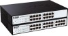
D-Link EasySmart Switch User Manual 2 Hardware Installation This chapter provides unpacking and installation information for the D-Link EasySmart Switch. Step 1: Unpacking Open the shipping carton and carefully unpack its contents. Please consult the packing list located in the User Manual to make sure all items are present and undamaged. If any item is missing or damaged, please contact your local D-Link reseller for replacement. One D-Link EasySmart Switch One AC power cord Four rubber feet Screws and two mounting brackets One accessory kit for a ground screw One Multi-lingual Getting Started Guide One CD with User Manual and SmartConsole Utility program If any item is found missing or damaged, please contact the local reseller for replacement. Step 2: Switch Installation For safe switch installation and operation, it is recommended that you: Visually inspect the power cord to see that it is secured fully to the AC power connector. Make sure that there is proper heat dissipation and adequate ventilation around the switch. Do not place heavy objects on the switch. Desktop or Shelf Installation When installing the switch on a desktop or shelf, the rubber feet included with the device must be attached on the bottom at each corner of the device's base. Allow enough ventilation space between the device and the objects around it. Figure 5 - Attach the adhesive rubber pads to the bottom Rack Installation The switch can be mounted in an EIA standard size 11-inch rack, which can be placed in a wiring closet with other equipment. To install, attach the mounting brackets to the switch's side panels (one on each side) and secure them with the screws provided (please note that these brackets are not designed for palm size switches). 4
-
 1
1 -
 2
2 -
 3
3 -
 4
4 -
 5
5 -
 6
6 -
 7
7 -
 8
8 -
 9
9 -
 10
10 -
 11
11 -
 12
12 -
13
-
14
-
15
-
16
-
17
-
18
-
19
-
20
-
21
-
22
-
23
-
24
-
25
-
26
-
27
-
28
-
29
-
30
-
31
-
32
-
33
-
34
-
35
-
36
-
37
-
38
-
39
-
40
 |
 |
