D-Link DGS-1210-10 Reference Guide - Page 10
DGS-1210-52, Front Panel, Rear Panel - 48 manual
 |
View all D-Link DGS-1210-10 manuals
Add to My Manuals
Save this manual to your list of manuals |
Page 10 highlights
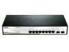
1 Product Introduction D-Link Web Smart Switch User Manual Power: The power port is where to connect the AC power cord. DGS-1210-52 48-Port 10/100/1000Mbps plus 4 1000Base-T/SFP Slot Web Smart Switch. Front Panel Figure 1.2 - DGS-1210-52 Front Panel Power LED : The Power LED lights up when the Switch is connected to a power source. Port Link/Act/Speed LED (1-48, 49F, 50F, 51F, 52F): The Link/Act/Speed LED flashes, which indicates a network link through the corresponding port. Blinking indicates that the Switch is either sending or receiving data to the port. When a port has an amber light, this indicates that the port is running on 10M or 100M. When it has a green light it is running on 1000M. Fan: The Fan LED lights green when fans work well, and lights red when fans fail. Reset: Press the Reset button for 5 seconds to reset the Switch back to the default settings. All previous changes will be lost. CAUTION: The MiniGBIC ports should use UL listed Optical Transceiver product, Rated Laser Class I. 3.3Vdc. Rear Panel Figure 1.3 - DGS-1210-52 Rear Panel Power: Connect the supplied AC power cable to this port. 5
-
 1
1 -
2
-
3
-
4
-
 5
5 -
 6
6 -
 7
7 -
 8
8 -
 9
9 -
 10
10 -
 11
11 -
 12
12 -
 13
13 -
 14
14 -
 15
15 -
16
-
17
-
18
-
19
-
20
-
21
-
22
-
23
-
24
-
25
-
26
-
27
-
28
-
29
-
30
-
31
-
32
-
33
-
34
-
35
-
36
-
37
-
38
-
39
-
40
-
41
-
42
-
43
-
44
-
45
-
46
-
47
-
48
-
49
-
50
-
51
-
52
-
53
-
54
-
55
-
56
-
57
-
58
-
59
-
60
-
61
-
62
-
63
-
64
-
65
-
66
-
67
-
68
-
69
-
70
-
71
-
72
-
73
-
74
-
75
-
76
-
77
-
78
-
79
-
80
-
81
-
82
-
83
-
84
-
85
-
86
-
87
-
88
-
89
-
90
-
91
-
92
-
93
-
94
 |
 |
