D-Link DGS-2208 User Manual - Page 17
Mounting the Switch on the Wall - dgs switch
 |
UPC - 790069291159
View all D-Link DGS-2208 manuals
Add to My Manuals
Save this manual to your list of manuals |
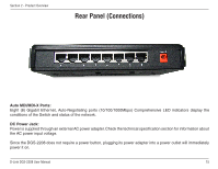
Page 17 highlights
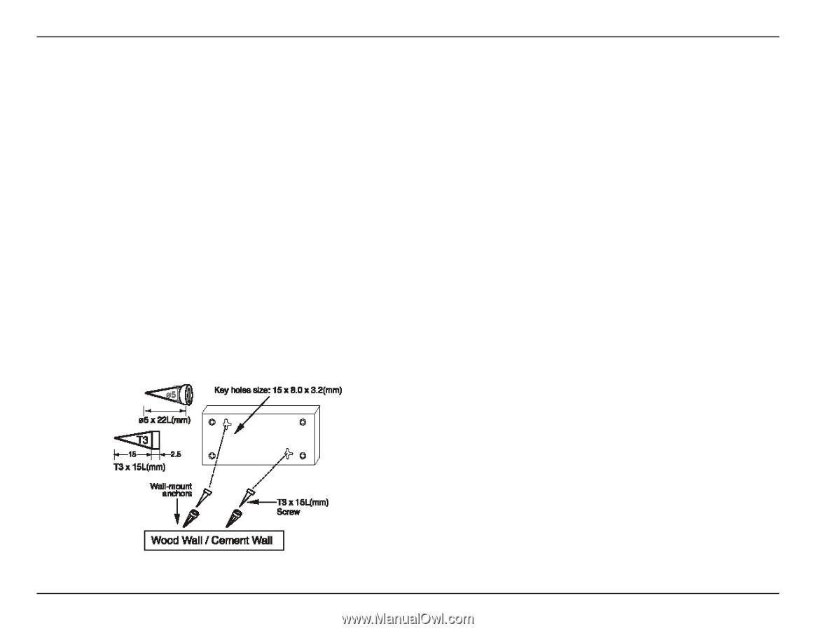
Section 3 - Installation Mounting the Switch on the Wall The DGS-2208 can also be mounted on a wall. Two mounting slots are provided on the bottom of the switch for this purpose. Please make sure that the front panel is exposed in order to view the LEDs. Please refer to the illustration below: Mounting on a cement wall 1. Mount the Nylon screw anchors into a cement wall. 2. Drive the T3 x 15L screws into the Nylon screw anchors. 3. Hook the mounting holes of the switch back on the screws. Mounting on a wood wall 1. Drive the T3 x 15 L screws into the wood wall. 2. Hook the mounting holes of the switch back on the screws. (1) 3/4 inch minimum for wood wall (2) 3 inch minimum for cement wall. D-Link DGS-2208 User Manual 17
-
 1
1 -
2
-
3
-
4
-
5
-
6
-
7
-
8
-
9
-
10
-
11
-
 12
12 -
 13
13 -
 14
14 -
 15
15 -
 16
16 -
 17
17 -
 18
18 -
 19
19 -
 20
20 -
 21
21 -
 22
22 -
23
-
24
-
25
-
26
-
27
-
28
-
29
-
30
-
31
-
32
-
33
-
34
-
35
-
36
-
37
 |
 |
17
D-Link DGS-2208 User Manual
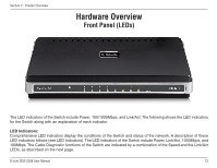
Section 3 - Installation
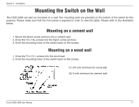
Mounting the Switch on the Wall
The DGS-2208 can also be mounted on a wall. Two mounting slots are provided on the bottom of the switch for this
purpose. Please make sure that the front panel is exposed in order to view the LEDs. Please refer to the illustration
below:
Mounting on a cement wall
1. Mount the Nylon screw anchors into a cement wall.
2. Drive the T3 x 15L screws into the Nylon screw anchors.
3. Hook the mounting holes of the switch back on the screws.
Mounting on a wood wall
1. Drive the T3 x 15 L screws into the wood wall.
2. Hook the mounting holes of the switch back on the screws.
(1) 3/4 inch minimum for wood wall
(2) 3 inch minimum for cement wall.