D-Link DGS-3620-52P Hardware Installation Guide - Page 47
Redundant Power Supply RPS Cable
 |
View all D-Link DGS-3620-52P manuals
Add to My Manuals
Save this manual to your list of manuals |
Page 47 highlights
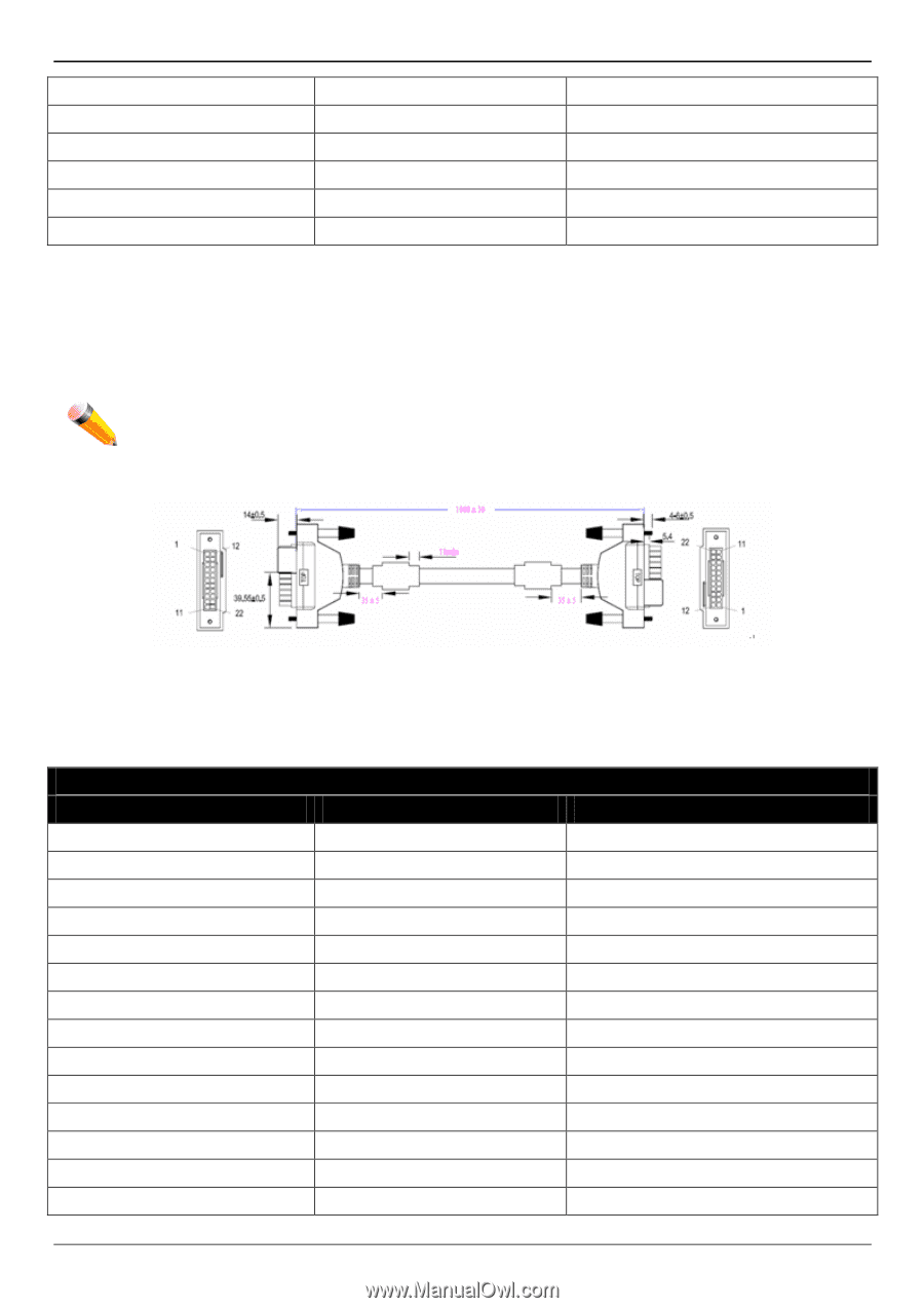
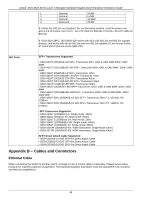
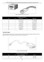
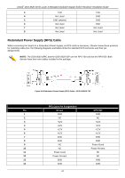
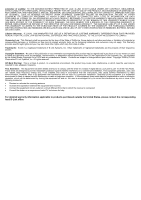
xStack® DGS-3620 Series Layer 3 Managed Stackable Gigabit Switch Hardware Installation Guide 3 TXD TXD 4 Not Used GND 5 GND (shared) GND 6 Not Used RXD 7 Not Used Not Used 8 Not Used Not Used Redundant Power Supply (RPS) Cable When connecting the Switch to a Redundant Power Supply, an RPS cable is necessary. Please review these products for matching cable pins.The following diagrams and tables show the standard RPS connector and their pin assignments. NOTE: The DGS-3620-28PC and the DGS-3620-52P use the RPS-700 and not the RPS-500. Both devices have their own cables included in the package. Figure 5-5 Redundant Power Supply (RPS) Cable - DPS-500/DPS-700 RPS Cable Pin Assignments Pin Device DPS-500 1 GND GND 2 NC NC 3 +12V +12V 4 +12V +12V 5 +12V +12V 6 +12V +12V 7 GND GND 8 GND GND 9 NC Power Good 10 NC Power Present 11 Power Good NC 12 Power Present NC 13 GND GND 14 GND GND 47
-
 1
1 -
2
-
3
-
4
-
5
-
6
-
7
-
8
-
9
-
10
-
11
-
12
-
13
-
14
-
15
-
16
-
17
-
18
-
19
-
20
-
21
-
22
-
23
-
24
-
25
-
26
-
27
-
28
-
29
-
30
-
31
-
32
-
33
-
34
-
35
-
36
-
37
-
38
-
39
-
40
-
41
-
 42
42 -
 43
43 -
 44
44 -
 45
45 -
 46
46 -
 47
47 -
 48
48 -
 49
49 -
 50
50 -
 51
51 -
 52
52 -
53
-
54
-
55
-
56
-
57
-
58
-
59
-
60
-
61
-
62
-
63
-
64
-
65
-
66
-
67
-
68
 |
 |