D-Link DGS-3630-28SC Product Manual - Page 25
LED Indicators, Side Panel Components, Switch GND, Appendix
 |
View all D-Link DGS-3630-28SC manuals
Add to My Manuals
Save this manual to your list of manuals |
Page 25 highlights
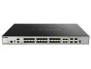
DGS-3630 Series Layer 3 Stackable Managed Switch Hardware Installation Guide Component Switch GND Description Use an electrical grounding wire and connect one end of the wire to the Switch GND and the other end of the wire to an electrical grounding point most commonly found on the Switch mounting rack itself. LED Indicators Located on the rear panel of this switch are LED indicators: USB and MGMT. LED USB MGMT Description This LED will light solid green if a USB flash drive is plugged in. This LED will blink green when the Switch is reading or writing data to and from the USB drive. This LED will be off when no USB drive is plugged into the USB port. This LED will light solid red when a USB drive failure has been detected. This LED will light solid green after a link to the MGMT port was successfully established. This LED will blink when activity on this port is taking place. This LED will be off when there is no link present or when this interface was shut down from within the Switch's configuration. Please refer to the "LED Indicators" section in the Appendix A - Technical Specifications for more LED information. Side Panel Components The side panels of this switch contain heat vents, fans, and rack-mounting screw holes. The heat vents are used to dissipate internal heat and facilitate internal air circulation. Do not block these openings. Leave at least 4 inches of space at the sides of the Switch for proper ventilation. Without proper heat dissipation and air circulation, system components might overheat which could lead to system failure or even severely damaged components. Figure 2-20 Side panels of the DGS-3630-52PC 25
-
 1
1 -
2
-
3
-
4
-
5
-
6
-
7
-
8
-
9
-
10
-
11
-
12
-
13
-
14
-
15
-
16
-
17
-
18
-
19
-
 20
20 -
 21
21 -
 22
22 -
 23
23 -
 24
24 -
 25
25 -
 26
26 -
 27
27 -
 28
28 -
 29
29 -
 30
30 -
31
-
32
-
33
-
34
-
35
-
36
-
37
-
38
-
39
-
40
-
41
-
42
-
43
-
44
-
45
-
46
-
47
-
48
-
49
-
50
-
51
-
52
-
53
-
54
-
55
-
56
-
57
-
58
-
59
-
60
-
61
-
62
-
63
-
64
-
65
-
66
-
67
-
68
-
69
-
70
-
71
-
72
-
73
-
74
-
75
-
76
-
77
-
78
-
79
-
80
-
81
-
82
-
83
 |
 |
