D-Link DGS-3630-52TC Product Manual
D-Link DGS-3630-52TC Manual
 |
View all D-Link DGS-3630-52TC manuals
Add to My Manuals
Save this manual to your list of manuals |
D-Link DGS-3630-52TC manual content summary:
- D-Link DGS-3630-52TC | Product Manual - Page 1
i - D-Link DGS-3630-52TC | Product Manual - Page 2
DGS-3630 Series Layer 3 Stackable Managed Switch Hardware Installation Guide Information in this document is subject to change without notice. Reproduction in any manner whatsoever, without the written permission of D-Link Corporation, is strictly forbidden. Trademarks used in this text: D-Link /108/ - D-Link DGS-3630-52TC | Product Manual - Page 3
Readers The DGS-3630 Series Layer 3 Stackable Managed Switch Hardware Installation Guide contains detailed information about the hardware specifications of the switches in this series. It also contains brief information on how to configure and manage a switch in this series. This manual is intended - D-Link DGS-3630-52TC | Product Manual - Page 4
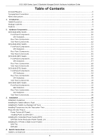
13 LED Indicators ...14 Rear Panel Components ...15 Side Panel Components ...15 DGS-3630-28PC Switch ...16 Front Panel Components...16 LED Indicators ...17 Rear Panel Components ...18 Side Panel Components ...19 DGS-3630-52TC Switch ...19 Front Panel Components...19 LED Indicators ...19 Rear Panel - D-Link DGS-3630-52TC | Product Manual - Page 5
DGS-3630 Series Layer 3 Stackable Managed Switch Hardware Installation Guide Switch to Another Switch ...36 Switch Stacking...37 (RPS) Cable ...61 Alarm Connector (RJ45) ...64 Safety/Sécurité ...65 Safety Instructions ...65 Safety Cautions ...65 Consignes de sécurité ...66 Précautions de sécurité - D-Link DGS-3630-52TC | Product Manual - Page 6
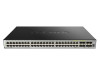
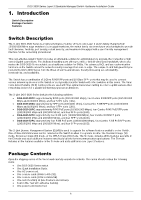
Guide 1. Introduction Switch Description Package Contents Features Switch Description The D-Link DGS-3630 Series is a high performance member of the D-Link Mbps and 100/1000 Mbps), and four SFP+ ports (10G). DGS-3630-28PC supports twenty RJ45 PoE ports (10/100/1000 Mbps), four Combo RJ45 PoE/SFP - D-Link DGS-3630-52TC | Product Manual - Page 7
DGS-3630 Series Layer 3 Stackable Managed Switch Hardware Installation Guide One CD containing the Web UI Reference Guide, CLI Reference Guide, D-View module, and additional software. If any item is missing or damaged, please contact your local D-Link MPLS OAM Class of Service (CoS) Two-rate Three - D-Link DGS-3630-52TC | Product Manual - Page 8
DGS-3630 Series Layer 3 Stackable Managed Switch Hardware Installation Guide Queue Handling: Strict Priority Queue (SPQ), Authentication Guest VLAN Microsoft® NAP Support (IPv4/IPv6) Trusted Host activated via ACL Cable Diagnostics 802.3ah Ethernet Link OAM (Dying Gasp on 10G ports) - D-Link DGS-3630-52TC | Product Manual - Page 9
DGS-3630 Series Layer 3 Stackable Managed Switch Hardware Installation Guide MIB, 802.1p MIB, IF MIB, RADIUS Authentication Client MIB, RADIUS Accounting Client MIB, Ping & TRACEROUTE MIB Table MIB, IPv6 SNMP MGMT Interface MIB, DDM MIB, LLDP-MED MIB, Private MIB, and D-Link Zone Defense. 9 - D-Link DGS-3630-52TC | Product Manual - Page 10
Guide 2. Hardware Components This chapter describes the front, rear, and side panel components of all switches in the series. DGS-3630-28TC Switch DGS-3630-28SC Switch DGS-3630-28PC Switch DGS-3630-52TC Switch DGS-3630-52PC Switch DGS-3630 and 1 Gbps wirespeeds and support a wide collection of SFP - D-Link DGS-3630-52TC | Product Manual - Page 11
Installation Guide LED Indicators Located on the front panel of this switch are LED indicators: Power, Console, RPS, Fan Err, USB, MGMT, Link/Act indicators for all the ports, and Stack ID. LED Power Console RPS Fan Err USB MGMT Link/Act LEDs Figure 2-2 LED indicators for the DGS-3630-28TC - D-Link DGS-3630-52TC | Product Manual - Page 12
LED Stack ID DGS-3630 Series Layer 3 Stackable Managed Switch Hardware Installation Guide Description This 7-segment LED can display numbers from 1 to 9 and the following letters H, h, E, and G. The stacking ID (1 to 9) can be assigned manually by the user or automatically by the system. The letter - D-Link DGS-3630-52TC | Product Manual - Page 13
Guide Figure 2-4 Side panels of the DGS-3630-28TC DGS-3630-28SC Switch Front Panel Components The front panel of DGS-3630-28SC features a variety of LED indicators and ports. Figure 2-5 Front panel view of the DGS-3630 Mbps and 1 Gbps wirespeeds and support a wide collection of SFP transceivers. - D-Link DGS-3630-52TC | Product Manual - Page 14
DGS-3630 Series Layer 3 Stackable Managed Switch Hardware Installation Guide For a complete list of SFP/SFP+ transceivers and Stack ID. LED Power Console RPS Fan Err USB MGMT Link/Act LEDs Figure 2-6 LED indicators for the DGS-3630-28SC Description This LED will light solid green after the Switch - D-Link DGS-3630-52TC | Product Manual - Page 15
LED Stack ID DGS-3630 Series Layer 3 Stackable Managed Switch Hardware Installation Guide Description This 7-segment LED can display numbers from 1 to 9 and the following letters H, h, E, and G. The stacking ID (1 to 9) can be assigned manually by the user or automatically by the system. The letter - D-Link DGS-3630-52TC | Product Manual - Page 16
Guide Figure 2-8 Side panels of the DGS-3630-28SC DGS-3630-28PC Switch Front Panel Components The front panel of DGS-3630-28PC features a variety of LED indicators, ports and a Mode button. Figure 2-9 Front panel view of the DGS-3630-28PC and 1 Gbps wire-speeds and support a wide collection of SFP - D-Link DGS-3630-52TC | Product Manual - Page 17
DGS-3630 Series Layer 3 Stackable Managed Switch Hardware Installation Guide CAUTION: This equipment is to be and Stack ID. LED Power Console RPS Fan Err USB MGMT Link/Act LEDs Figure 2-10 LED indicators for the DGS-3630-28PC Description This LED will light solid green after the Switch has been - D-Link DGS-3630-52TC | Product Manual - Page 18
DGS-3630 Series Layer 3 Stackable Managed Switch Hardware Installation Guide Description SFP+ Ports: This LED will light solid green when there is a connection (or link) to a 10 Gbps Ethernet device or solid amber when there is a connection (or link can be assigned manually by the user DGS-3630-28PC - D-Link DGS-3630-52TC | Product Manual - Page 19
DGS-3630 Series Layer 3 Stackable Managed Switch Hardware Installation Guide DGS-3630-28PC DGS-3630-52TC Switch Front Panel Components The front panel of DGS-3630 100 Mbps and 1 Gbps wirespeeds and support a wide collection of SFP transceivers. Link/Act indicators for all the ports, and Stack ID. 19 - D-Link DGS-3630-52TC | Product Manual - Page 20
Switch Hardware Installation Guide Figure 2-14 LED indicators for the DGS-3630-52TC LED Power Console RPS Fan Err Link/Act LEDs Stack following letters H, h, E, and G. The stacking ID (1 to 9) can be assigned manually by the user or automatically by the system. The letter 'H' will be displayed if - D-Link DGS-3630-52TC | Product Manual - Page 21
Layer 3 Stackable Managed Switch Hardware Installation Guide Figure 2-15 Rear panel view DGS-3630-52TC Components that can be found on has been detected. This LED will light solid green after a link to the MGMT port was successfully established. This LED will blink when activity on this port - D-Link DGS-3630-52TC | Product Manual - Page 22
LED DGS-3630 Series Layer 3 Stackable Managed Switch Hardware Installation Guide Description This LED will be off when there is no link speeds. The SFP ports can operate at 100 Mbps and 1 Gbps wire-speeds and support a wide collection of SFP transceivers. The Switch is equipped with 4 SFP/SFP+ - D-Link DGS-3630-52TC | Product Manual - Page 23
DGS-3630 Series Layer 3 Stackable Managed Switch Hardware Installation Guide CAUTION: This equipment is to be selection, and Stack ID. LED Power Console RPS Fan Err Link/Act LEDs PoE Figure 2-18 LED indicators for the DGS-3630-52PC Description This LED will light solid green after the Switch - D-Link DGS-3630-52TC | Product Manual - Page 24
LED Stack ID DGS-3630 Series Layer 3 Stackable Managed Switch Hardware Installation Guide Description This 7-segment LED can display numbers from 1 to 9 and the following letters H, h, E, and G. The stacking ID (1 to 9) can be assigned manually by the user or automatically by the system. The letter - D-Link DGS-3630-52TC | Product Manual - Page 25
DGS-3630 Series Layer 3 Stackable Managed Switch Hardware Installation Guide Component Switch GND Description Use when a USB drive failure has been detected. This LED will light solid green after a link to the MGMT port was successfully established. This LED will blink when activity on this port - D-Link DGS-3630-52TC | Product Manual - Page 26
DGS-3630 Series Layer 3 Stackable Managed Switch Hardware Installation Guide 3. Installation Installation Guidelines Installing the Switch feet to the Switch Install the Switch on a sturdy, level surface that can support the weight of the Switch (see the Weight section in Appendix A - Technical - D-Link DGS-3630-52TC | Product Manual - Page 27
DGS-3630 Series Layer 3 Stackable Managed Switch Hardware Installation Guide Installing the Switch in a Standard 19" Rack This section is used to guide connect various other networking devices to this switch that do not support the standard RJ45 wiring connection. These ports are generally used to - D-Link DGS-3630-52TC | Product Manual - Page 28
DGS-3630 Series Layer 3 Stackable Managed Switch Hardware Installation Guide used to connect devices to the Switch SFP+ ports. Figure 3-4 Inserting transceivers into the transceiver ports The SFP+ ports also support other transceiver form factors like SFP and SFP+ transceivers. A complete list of SFP - D-Link DGS-3630-52TC | Product Manual - Page 29
DGS-3630 Series Layer 3 Stackable Managed Switch Hardware Installation Guide Power Failure (AC Power) In the event install the power cord retainer together with the power cord. NOTE: The DGS-3630-28PC and DGS-3630-52PC do not support the installation of the power cord retainer. 1. With the rough side - D-Link DGS-3630-52TC | Product Manual - Page 30
DGS-3630 Series Layer 3 Stackable Managed Switch Hardware Installation Guide Figure 3-7 Slide the Retainer through the Tie Wrap 4. Circle the tie of the retainer around the power cord and into the locker of the retainer. Figure 3-8 Circle around the power cord 30 - D-Link DGS-3630-52TC | Product Manual - Page 31
DGS-3630 Series Layer 3 Stackable Managed Switch Hardware Installation Guide 5. Fasten the tie of the retainer until the power cord is secured. Figure 3-9 Secure the power cord Installing the Redundant Power Supply (RPS) The Redundant - D-Link DGS-3630-52TC | Product Manual - Page 32
Hardware Installation Guide Figure 3-10 Connecting a DGS-3630 Series supported. The DPS-500 can both be installed into a DPS-800 rack mount unit. The DPS-500 can only be used with the DGS-3630-28TC, DGS-3630-28SC, and DGS-3630-52TC. The DPS-700 can only be used with the DGS-3630-28PC and DGS-3630 - D-Link DGS-3630-52TC | Product Manual - Page 33
DGS-3630 Series Layer 3 Stackable Managed Switch Hardware Installation Guide Figure 3-11 Front view of the DPS-700 1. Insert one end Switch's firmware is needed for this installation. NOTE: See the RPS Quick Installation Guide for more information. Figure 3-12 Rear view of the DPS-700 connected to - D-Link DGS-3630-52TC | Product Manual - Page 34
Guide CAUTION: Do not connect the DPS-700 to the DGS-3630-28PC/52PC by using the 14-pin DC power cable. It may cause damage when using the wrong DC power cable. ONLY use the 22-pin DC power cable. ATTENTION : Ne connectez pas le DPS-700 au DGS-3630-28PC rack-mount chassis supports the following RPS - D-Link DGS-3630-52TC | Product Manual - Page 35
DGS-3630 Series Layer 3 Stackable Managed Switch Hardware Installation Guide Figure 3-14 Install the DPS-800 in an Equipment Rack 35 - D-Link DGS-3630-52TC | Product Manual - Page 36
DGS-3630 Series Layer 3 Stackable Managed Switch Hardware Installation Guide 4. Switch Connections Switch to an End port to the Switch via a twisted pair Category 5e UTP/STP cable. Connect a switch supporting an optical fiber uplink to the Switch's SFP/SFP+ ports via fiber optical cabling. Figure - D-Link DGS-3630-52TC | Product Manual - Page 37
Stackable Managed Switch Hardware Installation Guide Switch Stacking The DGS-3630 series supports stacking up to 9 switches increases overall reliability, serviceability, and availability. Duplex Chain - The Duplex Chain topology stacks switches together in a chain-link format. Using this - D-Link DGS-3630-52TC | Product Manual - Page 38
DGS-3630 Series Layer 3 Stackable Managed Switch Hardware Installation Guide The figure below illustrates how switches can be stacked in a Duplex Chain formation using optical fiber cables connected to SFP+ transceivers or DAC with SFP+ - D-Link DGS-3630-52TC | Product Manual - Page 39
DGS-3630 Series Layer 3 Stackable Managed Switch Hardware Installation Guide The figure below illustrates how switches can be stacked in a Duplex Ring formation using optical fiber cables connected to SFP+ transceivers or DAC with SFP+ - D-Link DGS-3630-52TC | Product Manual - Page 40
DGS-3630 Series Layer 3 Stackable Managed Switch Hardware Installation Guide Switch to a Server The Switch is ideal for connecting to a network backbone, server, or server farm. The RJ45 ports operate at a speed of 10/100/ - D-Link DGS-3630-52TC | Product Manual - Page 41
management features. For more detailed information about the CLI, refer to the DGS-3630 Series CLI Reference Guide. SNMP-based Management The Switch can be managed with an SNMP-compatible console program. The Switch supports SNMP v1, SNMPv2c and SNMPv3. The SNMP agent decodes the incoming SNMP - D-Link DGS-3630-52TC | Product Manual - Page 42
DGS-3630 Series Layer 3 Stackable Managed Switch Hardware Installation Guide Connect the male DB9 connector on the console cable (shipped with the Switch) to the RS-232 serial port on the computer running terminal emulation - D-Link DGS-3630-52TC | Product Manual - Page 43
DGS-3630 Series Layer 3 Stackable Managed Switch Hardware Installation Guide Connecting to the Mini-USB Console Port To use the mini-USB console port, the following equipment is needed: A terminal or a computer with a USB 2.0 port - D-Link DGS-3630-52TC | Product Manual - Page 44
DGS-3630 Series Layer 3 Stackable Managed Switch Hardware Installation Guide Figure 5-3 Device Manager Set the terminal emulation software as follows: Select the serial port that belongs to the virtual COM port. Set the data rate - D-Link DGS-3630-52TC | Product Manual - Page 45
DGS-3630 Series Layer 3 Stackable Managed Switch Hardware Installation Guide the Switch for the First Time The Switch supports user-based security that can prevent unauthorized DGS-3630-28PC Gigabit Ethernet Switch Switch> Command Line Interface Firmware: Build 2.25.018 Copyright(C) 2021 D-Link - D-Link DGS-3630-52TC | Product Manual - Page 46
DGS-3630 Series Layer 3 Stackable Managed Switch Hardware Installation Guide Creating a User Account One of the first and most important tasks will be to create user accounts. Logging in using a predefined administratorlevel username will give - D-Link DGS-3630-52TC | Product Manual - Page 47
DGS-3630 Series Layer 3 Stackable Managed Switch Hardware Installation Guide : Switch#show ip interface mgmt 0 mgmt_ipif 0 is enabled, Link status is up IP address is 192.168.0.1/24 Gateway is detect potential problems in the Switch, switch group, or network. Managed devices that support SNMP include - D-Link DGS-3630-52TC | Product Manual - Page 48
DGS-3630 Series Layer 3 Stackable Managed Switch Hardware Installation Guide The Switch allows groups of users to network management software. In addition to the standard MIB-II, the Switch also supports its own proprietary enterprise MIB as an extended Management Information Base. The proprietary - D-Link DGS-3630-52TC | Product Manual - Page 49
DGS-3630 Series Layer 3 Stackable Managed Switch Hardware Installation Guide 6. Web-based Switch Configuration with the Switch using the HTTP or HTTPS (SSL) protocol. The following web browsers are supported: Internet Explorer (version 7 and later) Firefox Google Chrome Safari Logging - D-Link DGS-3630-52TC | Product Manual - Page 50
DGS-3630 Series Layer 3 Stackable Managed Switch Hardware Installation Guide Web User Interface (Web UI) The Web UI management functions, including port monitoring, are accessible from here. Click the D-Link logo to go to the D-Link website. This area displays a file explorer-type menu tree with all - D-Link DGS-3630-52TC | Product Manual - Page 51
DGS-3630 Series Layer 3 Stackable Managed Switch Hardware Installation Guide in this folder. Features regarding the Quality of Service functionality of the Switch can be viewed and and configured in this folder. Features regarding the D-Link Green Technology can be viewed and configured in this - D-Link DGS-3630-52TC | Product Manual - Page 52
DGS-3630 Series Layer 3 Stackable Managed Switch Hardware Installation Guide Appendix A - Technical DGS-3630-28TC: Supports DPS-500 and DPS-800 DGS-3630-28SC: Supports DPS-500 and DPS-800 DGS-3630-28PC: Supports DPS-700 DGS-3630-52TC: Supports DPS-500 and DPS-800 DGS-3630-52PC: Supports - D-Link DGS-3630-52TC | Product Manual - Page 53
Hardware Installation Guide Feature Power Consumption Temperature Humidity Heat Dissipation Dimensions Weight MTBF EMC Certifications Safety Certifications Description DGS-3630-28TC: 42.4 Watts (Max.), 28.1 Watts (Standby) DGS-3630-28SC: 63.58 Watts (Max.), 30.1 Watts (Standby) DGS-3630-28PC: 44 - D-Link DGS-3630-52TC | Product Manual - Page 54
-28PC: 95.24 Mpps DGS-3630-52TC: 130.95 Mpps DGS-3630-52PC: 130.95 Mpps 8 Priority Queues per port. Supports 68K MAC addresses (SRM's LAN mode) Supports 1024 Static MAC addresses IPv4: 16K entries IPv6: 7K entries IPv4: 32K entries (SRM's IP mode) IPv6: 16K entries (SRM's IP mode) Supports D-Link - D-Link DGS-3630-52TC | Product Manual - Page 55
LED Mode Select Button to switch two modes in turn for all 10/100/1000Mbps ports on DGS-3630-28PC/52PC: Link/Act/Speed Mode PoE Mode Green Light on (Solid) An LED Mode Select Button to switch Link/Act/Speed Mode Light on (Solid) An LED Mode Select Button to switch PoE Mode Green - D-Link DGS-3630-52TC | Product Manual - Page 56
DGS-3630 Series Layer 3 Stackable Managed Switch Hardware Installation Guide Port Functions Feature standards: IEEE 802.3ae compliance IEEE 802.3z compliance IEEE 802.3ah compliance SFP Transceivers Supported: DEM-302S-LX (1000BASE-LX, single-mode, 2 km) DEM-310GT (1000BASE-LX, single - D-Link DGS-3630-52TC | Product Manual - Page 57
Feature DGS-3630 Series Layer 3 Stackable Managed Switch Hardware Installation Guide Description DEM-302S-BXD (1000BASE -331R (1000BASE-BX-U, single-mode, 20km, TX: 1310 nm / RX: 1550 nm) SFP+ Transceivers Supported: DEM-431XT (10GBASE-SR, multi-mode, 10 km, without DDM) DEM-431XT-DD (10GBASE - D-Link DGS-3630-52TC | Product Manual - Page 58
DGS-3630 Series Layer 3 Stackable Managed Switch Hardware Installation Guide Appendix B - Cables and Connectors Ethernet Cable When connecting the Switch to another switch, a bridge or hub, a straight-through Cat5/5e/6a/7 cable is necessary. Please - D-Link DGS-3630-52TC | Product Manual - Page 59
DGS-3630 Series Layer 3 Stackable Managed Switch Hardware Installation Guide Console Cable (RJ45 to RS-232) A console cable is used to connect to the RJ45 console port of the Switch to access the command line - D-Link DGS-3630-52TC | Product Manual - Page 60
DGS-3630 Series Layer 3 Stackable Managed Switch Hardware Installation Guide Console Cable (USB to Mini-USB) A console cable is used to connect to the USB console port of the Switch to access the command line - D-Link DGS-3630-52TC | Product Manual - Page 61
DGS-3630 Series Layer 3 Stackable Managed Switch Hardware Installation Guide Redundant Power Supply (RPS) Cable When connecting the Switch to a Redundant Power Supply, an RPS cable is necessary. Please review these products for matching cable - D-Link DGS-3630-52TC | Product Manual - Page 62
DGS-3630 Series Layer 3 Stackable Managed Switch Hardware Installation Guide 1 NC NC 2 GND GND 3 GND GND 4 GND GND 5 GND GND 6 +12V +12V 7 +12V +12V 8 +12V +12V 9 NC Power Present 10 NC Power Good 11 Power - D-Link DGS-3630-52TC | Product Manual - Page 63
DGS-3630 Series Layer 3 Stackable Managed Switch Hardware Installation Guide 8 +12Ven +12Ven 9 LS-54V LS-54V 10 -54V -54V 11 -54Vrtn -54Vrtn 12 GND NC/GND 13 GND GND 14 RPS Present Status_2 15 Status_1 - D-Link DGS-3630-52TC | Product Manual - Page 64
DGS-3630 Series Layer 3 Stackable Managed Switch Hardware Installation Guide Alarm Connector (RJ45) External devices can be connected to the alarm port to either trigger an alarm event or to be the recipient of an - D-Link DGS-3630-52TC | Product Manual - Page 65
DGS-3630 Series Layer 3 Stackable Managed Switch Hardware Installation Guide Safety/Sécurité Safety Instructions General Precautions for Rack-Mountable Products Protecting Against Electrostatic Discharge Safety Instructions the system gets wet contact your trained service provider. Do not push any - D-Link DGS-3630-52TC | Product Manual - Page 66
DGS-3630 Series Layer 3 Stackable Managed Switch Hardware Installation Guide to the Instructions. ATTENTION : Risque d'explosion si la batterie est remplacée par et remplacez la pièce concernée ou contactez votre prestataire de services agréé. Endommagement du câble d'alimentation, du câble de - D-Link DGS-3630-52TC | Product Manual - Page 67
DGS-3630 Series Layer 3 Stackable Managed Switch Hardware Installation Guide Danger électrique: Seul le fonctionner l'appareil dans un environnement humide. Si le système est mouillé, contactez votre prestataire de services qualifié. N'insérez aucun objet peripherals or supporting hardware: 67 - D-Link DGS-3630-52TC | Product Manual - Page 68
DGS-3630 Series Layer 3 Stackable Managed Switch Hardware Installation Guide de graves dommages corporels. Before working on the rack, make sure that stand on any component when servicing other components in a rack essayez pas de mettre le système sous tension si les câbles de mise à la masse ne sont - D-Link DGS-3630-52TC | Product Manual - Page 69
DGS-3630 Series Layer 3 Stackable Managed Switch Hardware Installation Guide Handle all sensitive components in a static-safe area. If possible, use antistatic floor pads, workbench pads and an antistatic grounding strap. 69 - D-Link DGS-3630-52TC | Product Manual - Page 70
price paid. Any repair or replacement will be rendered by D-Link at an Authorized D-Link Service customer must obtain a Case ID Number from D-Link Technical Support at 1-877-453-5465, who will attempt Do not include any manuals or accessories in the shipping package. D-Link will only replace the - D-Link DGS-3630-52TC | Product Manual - Page 71
WORK STOPPAGE, COMPUTER FAILURE OR MALFUNCTION, FAILURE OF OTHER EQUIPMENT OR COMPUTER PROGRAMS TO WHICH D-LINK LINK FOR WARRANTY SERVICE) RESULTING FROM THE USE OF THE PRODUCT, RELATING TO WARRANTY SERVICE, OR ARISING OUT OF ANY BREACH OF THIS LIMITED WARRANTY, EVEN IF D-LINK the instructions, may - D-Link DGS-3630-52TC | Product Manual - Page 72
Product Registration Register your D-Link product online at http://support.dlink.com/register/ Product registration is entirely voluntary and failure to complete or return this form will not diminish your warranty rights. - D-Link DGS-3630-52TC | Product Manual - Page 73
U.S. and Canadian customers This guide is only for initial configuration. Please refer to the user manual to learn more or visit http://www.mydlink.com for more information. Also feel free to contact us. U.S. and Canadian customers can contact D-Link Technical Support through our website. USA http - D-Link DGS-3630-52TC | Product Manual - Page 74
TÉCNICA SUPPORTO TECNICO TECHNISCHE ONDERSTEUNING POMOC TECHNICZNA TECHNICKÁ PODPORA TECHNIKAI TÁMOGATÁS TEKNISK STØTTE eu.dlink.com/support TEKNISK SUPPORT TEKNINEN TUKI TEKNISK SUPPORT ASSISTÊNCIA TÉCNICA TEHNIČKA PODRŠKA TEHNIČNA PODPORA SUPORT TEHNIC TECHNICKÁ PODPORA - D-Link DGS-3630-52TC | Product Manual - Page 75
vn Korea customers Tel : 1899-3540 Monday to Friday 9:30am to 6:30pm Web : http://d-link.co.kr E-mail : [email protected] New Zealand customers Tel: 0800-900-900 24/7 Technical Support Web: http://www.dlink.co.nz E-mail: [email protected] South Africa and Sub Sahara Region customers Tel: +27 12 - D-Link DGS-3630-52TC | Product Manual - Page 76
D-Link Middle East - Dubai, U.A.E. Plot No. S31102, Jebel Ali Free Zone South, P.O.Box 18224, Dubai, U.A.E. Tel: +971-4-8809022 Fax: +971-4-8809066 / 8809069 Technical Support: +971-4-8809033 General Inquiries: [email protected] Tech Support: [email protected] Egypt 19 Helmy El-Masry, - D-Link DGS-3630-52TC | Product Manual - Page 77
D-Link. D-Link D-Link D-Link D-Link: 8-800-700-5465 http://www.dlink.ru e-mail: [email protected] 114 3 289 390043 16 Тел.: +7 (4912) 503-505 - D-Link DGS-3630-52TC | Product Manual - Page 78
-8 Tel: +373 (22) 80-81-07 E-mail:[email protected] 169 Тэл.: +375 (17) 218-13-65 E-mail: [email protected] cі,143 7 (727) 378-55-90 E-mail: [email protected] 20 072-2575555 [email protected] 3 23/5 Հեռ.՝ +374 (10) 39-86-67 [email protected] Lietuva Vilnius, Žirmūnų 139-303 Tel - D-Link DGS-3630-52TC | Product Manual - Page 79
Por favor revise el número telefónico del Call Center de su país en http://www.dlinkla.com/soporte/call-center Soporte Técnico de D-Link a través de Internet Horario de atención Soporte Técnico en www.dlinkla.com e-mail: [email protected] & [email protected] Clientes de Brasil Caso tenha - D-Link DGS-3630-52TC | Product Manual - Page 80
D-Link D-Link 台灣D-Link 0800-002-615 02) 6600-0123#8715 http://www.dlink.com.tw [email protected] http://www.dlink.com.tw D-Link 852) 8100 8892 http://www.dlink.com.hk [email protected] http://www.dlink.com.hk/contact.html D-Link網站www.dlink.com - D-Link DGS-3630-52TC | Product Manual - Page 81
. Dukungan Teknis untuk pelanggan: Tel: 0800-14014-97 (Layanan Bebas Pulsa) Dukungan Teknis D-Link melalui Internet: Pertanyaan Umum: [email protected] Bantuan Teknis: [email protected] Website : http://www.dlink.co.id 中國客戶 4006-828-828 9:00-18:00 [email protected] http://www - D-Link DGS-3630-52TC | Product Manual - Page 82
to the following questions help us to support your product: 1. Where and how will Company Business Home Business Personal Use 2. How many employees work at installation site? 1 employee 2-9 10-49 50- operating system(s) does your organization use ? D-Link LANsmart Novell NetWare NetWare Lite SCO Unix/ - D-Link DGS-3630-52TC | Product Manual - Page 83
-
 1
1 -
 2
2 -
 3
3 -
 4
4 -
 5
5 -
 6
6 -
 7
7 -
8
-
9
-
10
-
11
-
12
-
13
-
14
-
15
-
16
-
17
-
18
-
19
-
20
-
21
-
22
-
23
-
24
-
25
-
26
-
27
-
28
-
29
-
30
-
31
-
32
-
33
-
34
-
35
-
36
-
37
-
38
-
39
-
40
-
41
-
42
-
43
-
44
-
45
-
46
-
47
-
48
-
49
-
50
-
51
-
52
-
53
-
54
-
55
-
56
-
57
-
58
-
59
-
60
-
61
-
62
-
63
-
64
-
65
-
66
-
67
-
68
-
69
-
70
-
71
-
72
-
73
-
74
-
75
-
76
-
77
-
78
-
79
-
80
-
81
-
82
-
83
 |
 |

i