D-Link DGS-3630-52TC HW Installation Guide
D-Link DGS-3630-52TC Manual
 |
View all D-Link DGS-3630-52TC manuals
Add to My Manuals
Save this manual to your list of manuals |
D-Link DGS-3630-52TC manual content summary:
- D-Link DGS-3630-52TC | HW Installation Guide - Page 1
- D-Link DGS-3630-52TC | HW Installation Guide - Page 2
Series Layer 3 Stackable Managed Switch Hardware Installation Guide Information in this document is subject to change without radio frequency energy and, if not installed and used in accordance with this manual, may cause harmful interference to radio communications. Operation of this equipment in - D-Link DGS-3630-52TC | HW Installation Guide - Page 3
Guide contains detailed information about the hardware specifications of the switches in this series. It also contains brief information on how to configure and manage a switch in this series. This manual death. Safety Instructions Please pay part or contact your trained service provider: Damage to - D-Link DGS-3630-52TC | HW Installation Guide - Page 4
Managed Switch Hardware Installation Guide The product does not operate correctly when the operating instructions are correctly followed. General a wet environment. If the system gets wet contact your trained service provider. Do not push any objects into the openings of supporting hardware: iv - D-Link DGS-3630-52TC | HW Installation Guide - Page 5
3630 Series Layer 3 Stackable Managed Switch Hardware Installation Guide CAUTION: Installing systems in a rack without the components in the rack. Do not step on or stand on any component when servicing other components in a rack. CAUTION: Never defeat the ground conductor or operate the equipment - D-Link DGS-3630-52TC | HW Installation Guide - Page 6
DGS-3630 Series Layer 3 Stackable Managed Switch Hardware Installation Guide Table of Contents Intended Readers ...3 Typographical Conventions ...3 Notes and Cautions ...3 Safety Instructions ...3 Safety Cautions ...3 General Precautions for Rack-Mountable Products ...4 Protecting Against - D-Link DGS-3630-52TC | HW Installation Guide - Page 7
DGS-3630 Series Layer 3 Stackable Managed Switch Hardware Installation Guide Connecting to the Switch for the First Time...39 Creating a User Account...39 Configuring the IP Address...40 Connecting to the MGMT Port ...40 Connecting - D-Link DGS-3630-52TC | HW Installation Guide - Page 8
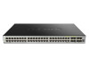
viruses, thereby increasing overall reliability, serviceability, and availability. The Switch has and four SFP+ ports (10G). DGS-3630-28SC supports twenty SFP ports (100/1000 Mbps), four Combo RJ45 One DGS-3630 Series switch. One Quick Installation Guide. One AC power cord. One console cable - D-Link DGS-3630-52TC | HW Installation Guide - Page 9
Guide Features This switch is packed with an abundance of networking features that span inside and outside of the traditional Layer 3 framework. The list below highlights the significant protocols and features supported VRF-Lite, and MPLS OAM Class of Service (CoS) Two-rate Three-color Marker ( - D-Link DGS-3630-52TC | HW Installation Guide - Page 10
3630 Series Layer 3 Stackable Managed Switch Hardware Installation Guide Access Control List (ACL): IP Access MAC-based Access Control (MAC) Compound Authentication Guest VLAN Microsoft® NAP Support (IPv4/IPv6) Trusted Host activated via ACL Cable Diagnostics 802.3ah Ethernet Link - D-Link DGS-3630-52TC | HW Installation Guide - Page 11
DGS-3630 Series Layer 3 Stackable Managed Switch Hardware Installation Guide LLDP-MED MIB, Private MIB, and D-Link Zone Defense. 11 - D-Link DGS-3630-52TC | HW Installation Guide - Page 12
Layer 3 Stackable Managed Switch Hardware Installation Guide 2. Hardware Components This chapter describes the front Gbps wire-speeds. The SFP ports can operate at 100 Mbps and 1 Gbps wire-speeds and support a wide collection of SFP transceivers. The Switch is equipped with 4 SFP/SFP+ ports. These - D-Link DGS-3630-52TC | HW Installation Guide - Page 13
Series Layer 3 Stackable Managed Switch Hardware Installation Guide LED Indicators Located on the front panel of 9 and the following letters H, h, E, and G. The stacking ID (1 to 9) can be assigned manually by the user or automatically by the system. The letter 'H' will be displayed if this switch is - D-Link DGS-3630-52TC | HW Installation Guide - Page 14
LED DGS-3630 Series Layer 3 Stackable Managed Switch Hardware Installation Guide Description The letter 'h' will be displayed if this switch is the backup master switch in the stack. The letter 'E' will be displayed if there was - D-Link DGS-3630-52TC | HW Installation Guide - Page 15
Series Layer 3 Stackable Managed Switch Hardware Installation Guide Figure 2-4 Side panels of the DGS-3630- 1 Gbps wire-speeds. The SFP ports can operate at 100 Mbps and 1 Gbps wire-speeds and support a wide collection of SFP transceivers. The Switch is equipped with 4 SFP/SFP+ ports. These ports - D-Link DGS-3630-52TC | HW Installation Guide - Page 16
DGS-3630 Series Layer 3 Stackable Managed Switch Hardware Installation Guide LED Indicators Located on the front panel of this switch are LED indicators: Power, Console, RPS from 1 to 9 and the following letters H, h, E, and G. The stacking ID (1 to 9) can be assigned manually by the user or 16 - D-Link DGS-3630-52TC | HW Installation Guide - Page 17
LED DGS-3630 Series Layer 3 Stackable Managed Switch Hardware Installation Guide Description automatically by the system. The letter 'H' will be displayed if this switch is the master switch in the stack. The letter 'h' will be displayed - D-Link DGS-3630-52TC | HW Installation Guide - Page 18
Series Layer 3 Stackable Managed Switch Hardware Installation Guide Figure 2-8 Side panels of the DGS-3630- 1 Gbps wire-speeds. The SFP ports can operate at 100 Mbps and 1 Gbps wire-speeds and support a wide collection of SFP transceivers. The Switch is equipped with 4 SFP/SFP+ ports. These ports - D-Link DGS-3630-52TC | HW Installation Guide - Page 19
Layer 3 Stackable Managed Switch Hardware Installation Guide LED Power Console RPS Fan Err Link/ to 9 and the following letters H, h, E, and G. The stacking ID (1 to 9) can be assigned manually by the user or automatically by the system. The letter 'H' will be displayed if this switch is the master - D-Link DGS-3630-52TC | HW Installation Guide - Page 20
DGS-3630 Series Layer 3 Stackable Managed Switch Hardware Installation Guide Components that can be found on the rear panel of this switch are listed in the table below. Component Description Security Lock Switch GND AC - D-Link DGS-3630-52TC | HW Installation Guide - Page 21
DGS-3630 Series Layer 3 Stackable Managed Switch Hardware Installation Guide Side Panel Components The side panels of this switch contain heat vents, fans, and rack-mounting screw holes. The heat vents are used to dissipate - D-Link DGS-3630-52TC | HW Installation Guide - Page 22
to sunlight. Installing the Switch without a Rack This section is used to guide the user through installing the Switch in an area other than a switch rack to the Switch Install the Switch on a sturdy, level surface that can support the weight of the Switch (see the Weight section in Appendix A - - D-Link DGS-3630-52TC | HW Installation Guide - Page 23
Switch in a Standard 19" Rack This section is used to guide the user through installing the Switch into a switch rack. be used to connect various other networking devices to this switch that do not support the standard RJ45 wiring connection. These ports are generally used to connect this switch to - D-Link DGS-3630-52TC | HW Installation Guide - Page 24
Series Layer 3 Stackable Managed Switch Hardware Installation Guide used to connect devices to the Switch over SFP+ ports. Figure 3-4 Inserting transceivers into the transceiver ports The SFP+ ports also support other transceiver form factors like SFP and SFP+ transceivers. A complete list of SFP/ - D-Link DGS-3630-52TC | HW Installation Guide - Page 25
DGS-3630 Series Layer 3 Stackable Managed Switch Hardware Installation Guide Figure 3-5 Insert Tie Wrap into the Switch 2. Plug the AC power cord into the power socket of the Switch. Figure 3-6 Connect the power cord to - D-Link DGS-3630-52TC | HW Installation Guide - Page 26
DGS-3630 Series Layer 3 Stackable Managed Switch Hardware Installation Guide Figure 3-7 Slide the Retainer through the Tie Wrap 4. Circle the tie of the retainer around the power cord and into the locker of the retainer. Figure 3-8 Circle around the power cord 26 - D-Link DGS-3630-52TC | HW Installation Guide - Page 27
Series Layer 3 Stackable Managed Switch Hardware Installation Guide 5. Fasten the tie of the retainer until power supply on the other end. The RPS provides a lowcost, simple solution to the problem of an inadvertent failure of the internal power supply of an Ethernet switch, which can result - D-Link DGS-3630-52TC | HW Installation Guide - Page 28
Series Layer 3 Stackable Managed Switch Hardware Installation Guide Figure 3-10 Connecting a DGS-3630 Series rack-mountable unit designed to hold up to two RPS units. NOTE: This rack-mount chassis supports the following RPS units: DPS-500A and DPS-500DC. The following diagram illustrates how a DPS- - D-Link DGS-3630-52TC | HW Installation Guide - Page 29
DGS-3630 Series Layer 3 Stackable Managed Switch Hardware Installation Guide Figure 3-12 Install the DPS-800 in an Equipment Rack 29 - D-Link DGS-3630-52TC | HW Installation Guide - Page 30
Series Layer 3 Stackable Managed Switch Hardware Installation Guide 4. Switch Connections Switch to an End Node port to the Switch via a twisted pair Category 5e UTP/STP cable. Connect a switch supporting an optical fiber uplink to the Switch's SFP/SFP+ ports via fiber optical cabling. Figure - D-Link DGS-3630-52TC | HW Installation Guide - Page 31
Layer 3 Stackable Managed Switch Hardware Installation Guide Switch Stacking The DGS-3630 series supports stacking up to 9 switches together while ports to scale and stack the Switches. This increases overall reliability, serviceability, and availability. Duplex Chain - The Duplex Chain topology - D-Link DGS-3630-52TC | HW Installation Guide - Page 32
DGS-3630 Series Layer 3 Stackable Managed Switch Hardware Installation Guide The figure below illustrates how switches can be stacked in a Duplex Chain formation using optical fiber cables connected to SFP+ transceivers or DAC with SFP+ - D-Link DGS-3630-52TC | HW Installation Guide - Page 33
DGS-3630 Series Layer 3 Stackable Managed Switch Hardware Installation Guide The figure below illustrates how switches can be stacked in a Duplex Ring formation using optical fiber cables connected to SFP+ transceivers or DAC with SFP+ - D-Link DGS-3630-52TC | HW Installation Guide - Page 34
DGS-3630 Series Layer 3 Stackable Managed Switch Hardware Installation Guide Switch to a Server The Switch is ideal for connecting to a network backbone, server, or server farm. The RJ45 ports operate at a speed of 10/100/ - D-Link DGS-3630-52TC | HW Installation Guide - Page 35
. For more detailed information about the CLI, refer to the DGS-3630 Series CLI Reference Guide. SNMP-based Management The Switch can be managed with an SNMP-compatible console program. The Switch supports SNMP v1, SNMPv2c and SNMPv3. The SNMP agent decodes the incoming SNMP messages and responds - D-Link DGS-3630-52TC | HW Installation Guide - Page 36
DGS-3630 Series Layer 3 Stackable Managed Switch Hardware Installation Guide Connect the male DB9 connector on the console cable (shipped with the Switch) to the RS-232 serial port on the computer running terminal emulation - D-Link DGS-3630-52TC | HW Installation Guide - Page 37
DGS-3630 Series Layer 3 Stackable Managed Switch Hardware Installation Guide Connecting to the Mini-USB Console Port To use the mini-USB console port, the following equipment is needed: A terminal or a computer with a USB 2.0 port - D-Link DGS-3630-52TC | HW Installation Guide - Page 38
DGS-3630 Series Layer 3 Stackable Managed Switch Hardware Installation Guide Set the terminal emulation software as follows: Select the serial port that belongs to the virtual COM port. Set the data rate to 115200 baud. - D-Link DGS-3630-52TC | HW Installation Guide - Page 39
Series Layer 3 Stackable Managed Switch Hardware Installation Guide NOTE: After a connection to the mini-USB establish a new connection. Connecting to the Switch for the First Time The Switch supports user-based security that can prevent unauthorized users from accessing the Switch or changing its - D-Link DGS-3630-52TC | HW Installation Guide - Page 40
DGS-3630 Series Layer 3 Stackable Managed Switch Hardware Installation Guide 4. Enter the username NewUser privilege 15 command. Press Enter. This will configure this user account to have Administrative (15) privileges. 5. Enter the line console command - D-Link DGS-3630-52TC | HW Installation Guide - Page 41
Series Layer 3 Stackable Managed Switch Hardware Installation Guide Switch#configure terminal Switch(config)#interface mgmt 0 operation, monitor performance, and detect potential problems in the Switch, switch group, or network. Managed devices that support SNMP include software (referred to as an - D-Link DGS-3630-52TC | HW Installation Guide - Page 42
Series Layer 3 Stackable Managed Switch Hardware Installation Guide Management Information Base (MIB) A Management Information management software. In addition to the standard MIB-II, the Switch also supports its own proprietary enterprise MIB as an extended Management Information Base. The - D-Link DGS-3630-52TC | HW Installation Guide - Page 43
Layer 3 Stackable Managed Switch Hardware Installation Guide 6. Web-based Switch Configuration Introduction Logging with the Switch using the HTTP or HTTPS (SSL) protocol. The following web browsers are supported: Internet Explorer (version 7 and later) Firefox Google Chrome Safari Logging - D-Link DGS-3630-52TC | HW Installation Guide - Page 44
DGS-3630 Series Layer 3 Stackable Managed Switch Hardware Installation Guide NOTE: After a user account was created, login credentials will be required to access the Web UI. During the sending and receiving of the login password - D-Link DGS-3630-52TC | HW Installation Guide - Page 45
4 DGS-3630 Series Layer 3 Stackable Managed Switch Hardware Installation Guide This area displays a file explorer-type menu tree with all be viewed and configured in this folder. Features regarding the Quality of Service functionality of the Switch can be viewed and configured in this folder. - D-Link DGS-3630-52TC | HW Installation Guide - Page 46
Series Layer 3 Stackable Managed Switch Hardware Installation Guide Appendix A - Technical Specifications General Feature Data Ports: Up to 9 switches can be stacked using the 10 Gbps SFP+ ports Backup Master Support: Yes UTP/STP Category 3, 4, 5 for 10BASE-T UTP/STP Category.5, 5e for 100BASE-TX - D-Link DGS-3630-52TC | HW Installation Guide - Page 47
Layer 3 Stackable Managed Switch Hardware Installation Guide Feature Dimensions Weight MTBF EMC Certifications 24 Mpps DGS-3630-52TC: 130.95 Mpps 8 Priority Queues per port. Supports 68K MAC addresses (SRM's LAN mode) Supports 1024 Static MAC addresses IPv4: 16K entries IPv6: 7K entries IPv4: 32K - D-Link DGS-3630-52TC | HW Installation Guide - Page 48
DGS-3630 Series Layer 3 Stackable Managed Switch Hardware Installation Guide LED Indicators Location Per Device LED Per 10/100/1000 Mbps Port LED per SFP Port LED Power MGMT Console Fan Err RPS USB Stacking - D-Link DGS-3630-52TC | HW Installation Guide - Page 49
Layer 3 Stackable Managed Switch Hardware Installation Guide Location LED per SFP+ Port LED Link 50 km) DEM-315GT (1000BASE-ZX, single-mode, 80 km) DGS-712 (1000BASE-T) WDM (BiDi) SFP Transceivers Supported: DEM-220T (100BASE-BX-D, single-mode, 20 km, TX: 1550 nm / RX: 1310 nm) DEM-220R ( - D-Link DGS-3630-52TC | HW Installation Guide - Page 50
Series Layer 3 Stackable Managed Switch Hardware Installation Guide Feature SFP+ Ports Description DEM-330R ( DDM) DEM-434XT (10GBASE-ZR, single-mode, 80 km, without DDM) WDM (BiDi) SFP+ Transceivers Supported: DEM-436XT-BXD (10GBASE-LR, single-mode, 20 km, TX: 1330 nm / RX: 1270 nm, - D-Link DGS-3630-52TC | HW Installation Guide - Page 51
DGS-3630 Series Layer 3 Stackable Managed Switch Hardware Installation Guide Appendix B - Cables and Connectors Ethernet Cable When connecting the Switch to another switch, a bridge or hub, a straight-through Cat5/5e/6a/7 cable is necessary. Please - D-Link DGS-3630-52TC | HW Installation Guide - Page 52
DGS-3630 Series Layer 3 Stackable Managed Switch Hardware Installation Guide Console Cable (RJ45 to RS-232) A console cable is used to connect to the RJ45 console port of the Switch to access the command line - D-Link DGS-3630-52TC | HW Installation Guide - Page 53
DGS-3630 Series Layer 3 Stackable Managed Switch Hardware Installation Guide Console Cable (USB to Mini-USB) A console cable is used to connect to the USB console port of the Switch to access the command line - D-Link DGS-3630-52TC | HW Installation Guide - Page 54
DGS-3630 Series Layer 3 Stackable Managed Switch Hardware Installation Guide Redundant Power Supply (RPS) Cable When connecting the Switch to a Redundant Power Supply, an RPS cable is necessary. Please review this product for matching cable - D-Link DGS-3630-52TC | HW Installation Guide - Page 55
DGS-3630 Series Layer 3 Stackable Managed Switch Hardware Installation Guide Alarm Connector (RJ45) External devices can be connected to the alarm port to either trigger an alarm event or to be the recipient of an - D-Link DGS-3630-52TC | HW Installation Guide - Page 56
be rendered by D-Link at an Authorized D-Link Service Office. The replacement hardware need not be new or obtain a Case ID Number from D-Link Technical Support at 1-877-453-5465, who will attempt to outside of the package. Do not include any manuals or accessories in the shipping package. D-Link will - D-Link DGS-3630-52TC | HW Installation Guide - Page 57
WITH ANY PRODUCT RETURNED TO D-LINK FOR WARRANTY SERVICE) RESULTING FROM THE USE OF THE PRODUCT, RELATING TO WARRANTY SERVICE, OR ARISING OUT OF ANY BREACH OF THIS and, if not installed and used in accordance with the instructions, may cause harmful interference to radio communication. However, there - D-Link DGS-3630-52TC | HW Installation Guide - Page 58
Product Registration Register your D-Link product online at http://support.dlink.com/register/ Product registration is entirely voluntary and failure to complete or return this form will not diminish your warranty rights. - D-Link DGS-3630-52TC | HW Installation Guide - Page 59
U.S. and Canadian customers This guide is only for initial configuration. Please refer to the user manual to learn more or visit http://www.mydlink.com for more information. Also feel free to contact us. U.S. and Canadian customers can contact D-Link Technical Support through our website. USA http - D-Link DGS-3630-52TC | HW Installation Guide - Page 60
ÜTZUNG ASSISTANCE TECHNIQUE ASISTENCIA TÉCNICA SUPPORTO TECNICO TECHNISCHE ONDERSTEUNING POMOC TECHNICZNA TECHNICKÁ PODPORA TECHNICKÁ PODPORA TECHNIKAI TÁMOGATÁS TEKNISK SUPPORT TEKNISK SUPPORT TEKNISK STØTTE TEKNINEN TUKI ASSISTÊNCIA TÉCNICA TEHNIČKA PODRŠKA TEHNIČNA PODPORA SUPORT TEHNIC dlink - D-Link DGS-3630-52TC | HW Installation Guide - Page 61
Australia customers Tel: 1300-700-100 24/7 Technical Support Web: http://www.dlink.com.au E-mail: [email protected] India customers Tel: +91-832-2856000 Toll Free 1800-233-0000 mail : [email protected] New Zealand customers Tel: 0800-900-900 24/7 Technical Support Web: http://www.dlink.co.nz E-mail - D-Link DGS-3630-52TC | HW Installation Guide - Page 62
12 661 2025 08600 DLINK (for South Africa only) Monday to Friday 8:30am to 9:00pm South Africa Time Web: http://www.d-link.co.za E-mail: [email protected] D-Link Middle East - Dubai, U.A.E. customers Plot No. S31102, Jebel Ali Free Zone South, P.O.Box 18224, Dubai, U.A.E. Tel: +971-4-8809022 Fax - D-Link DGS-3630-52TC | HW Installation Guide - Page 63
, Argentine Sq. , Tehran IRAN Postal Code : 1513833817 Tel: +98-21-88880918,19 +98-21-88706653,54 General Inquiries: [email protected] Tech Support: [email protected] Morocco customers M.I.T.C Route de Nouaceur angle RS et CT 1029 Bureau N° 312 ET 337 Casablanca , Maroc Phone : +212 663 72 - D-Link DGS-3630-52TC | HW Installation Guide - Page 64
54 49 71 Ext:14 Fax: +961 4 54 49 71 Ext:12 Email: [email protected] Bahrain customers Technical Support: +973 1 3332904 Kuwait customers Technical Support: + 965 22453939 / +965 22453949 Türkiye customers Büyükdere Cad. Ferro Plaza No:155 D: 1 K: 1 Zincirlikuyu / Istanbul Tel: +90 (212) 289-56 - D-Link DGS-3630-52TC | HW Installation Guide - Page 65
Link D-Link D-Link: 8-800-700-5465 http://www.dlink.ru e-mail: [email protected] Офисы 14 Тел. : +7 (495) 744-00-99 E-mail: 373(22) 80-81-07 E-mail:[email protected] 169 Тэл.: +375 (17) 218-13-65 E-mail: [email protected] 143 7 (727) 378-55-90 E-mail: [email protected] 3 23/5 Հեռ.՝ +374 (10 - D-Link DGS-3630-52TC | HW Installation Guide - Page 66
Soporte Técnico Para Usuarios En Latino America Por favor revise el número telefónico del Call Center de su país en http://www.dlinkla.com/soporte/call-center Soporte Técnico de D-Link a través de Internet Horario de atención Soporte Técnico en www.dlinkla.com e-mail: [email protected] & consultas - D-Link DGS-3630-52TC | HW Installation Guide - Page 67
Clientes de Brasil Caso tenha dúvidas na instalação do produto, entre em contato com o Suporte Técnico D-Link. Acesse o site: www.dlink.com.br/suporte - D-Link DGS-3630-52TC | HW Installation Guide - Page 68
@dlink.com.tw http://www.dlink.com.tw D-Link 852) 8100 8892 10:00 ~ 19:00 週六: 09:00~13:00 http://www.dlink.com.hk [email protected] 202-210 1樓A室 178號-188 16樓02室 D-Link網站www.dlink.com - D-Link DGS-3630-52TC | HW Installation Guide - Page 69
dapat diperoleh pada situs web D-Link. Dukungan Teknis untuk pelanggan: Tel: 0800-14014-97 (TOLL FREE) Dukungan Teknis D-Link melalui Internet: Email : [email protected] Website : http://www.dlink.co.id 中國客戶 400-629-6688 [email protected] http://www.dlink.com.cn 400 9:00-19:00 - D-Link DGS-3630-52TC | HW Installation Guide - Page 70
serial No. (* Applies to adapters only) Product was purchased from: Reseller's name Telephone Answers to the following questions help us to support your product: 1. Where and how will the product primarily be used? Home Office Travel Company Business Home Business Personal Use 2. How many - D-Link DGS-3630-52TC | HW Installation Guide - Page 71
-
 1
1 -
 2
2 -
 3
3 -
 4
4 -
 5
5 -
 6
6 -
 7
7 -
8
-
9
-
10
-
11
-
12
-
13
-
14
-
15
-
16
-
17
-
18
-
19
-
20
-
21
-
22
-
23
-
24
-
25
-
26
-
27
-
28
-
29
-
30
-
31
-
32
-
33
-
34
-
35
-
36
-
37
-
38
-
39
-
40
-
41
-
42
-
43
-
44
-
45
-
46
-
47
-
48
-
49
-
50
-
51
-
52
-
53
-
54
-
55
-
56
-
57
-
58
-
59
-
60
-
61
-
62
-
63
-
64
-
65
-
66
-
67
-
68
-
69
-
70
-
71
 |
 |