D-Link DGS-3630-52TC HW Installation Guide - Page 18
DGS-3630-52TC Switch, Front Panel Components, LED Indicators
 |
View all D-Link DGS-3630-52TC manuals
Add to My Manuals
Save this manual to your list of manuals |
Page 18 highlights
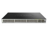
DGS-3630 Series Layer 3 Stackable Managed Switch Hardware Installation Guide Figure 2-8 Side panels of the DGS-3630-28SC DGS-3630-52TC Switch Front Panel Components The front panel of DGS-3630-52TC features a variety of LED indicators and ports. Figure 2-9 Front panel view of the DGS-3630-52TC Ports that can be found on the front panel of this switch are listed in the table below. Port Description 10/100/1000 Mbps RJ45 Ports Combo RJ45/SFP Ports 10 Gigabit SFP+ Ports The Switch is equipped with 44 RJ45 Ethernet ports. These ports can operate at 10 Mbps, 100 Mbps, and 1 Gbps wire-speeds. The Switch is equipped with 4 combo ports that can either operate as RJ45 Ethernet ports or SFP ports. The RJ45 ports can operate at 10 Mbps, 100 Mbps, and 1 Gbps wire-speeds. The SFP ports can operate at 100 Mbps and 1 Gbps wire-speeds and support a wide collection of SFP transceivers. The Switch is equipped with 4 SFP/SFP+ ports. These ports can operate at 1 Gbps and 10 Gbps wire-speeds and support a wide collection of SFP/SFP+ transceivers. For a complete list of SFP/SFP+ transceivers that are compatible with this switch, refer to the SFP Ports and SFP+ Ports sections in Appendix A - Technical Specifications. LED Indicators Located on the front panel of this switch are LED indicators: Power, Console, RPS, Fan Err, Link/Act indicators for all the ports, and Stack ID. Figure 2-10 LED indicators for the DGS-3630-52TC 18
-
 1
1 -
2
-
3
-
4
-
5
-
6
-
7
-
8
-
9
-
10
-
11
-
12
-
 13
13 -
 14
14 -
 15
15 -
 16
16 -
 17
17 -
 18
18 -
 19
19 -
 20
20 -
 21
21 -
 22
22 -
 23
23 -
24
-
25
-
26
-
27
-
28
-
29
-
30
-
31
-
32
-
33
-
34
-
35
-
36
-
37
-
38
-
39
-
40
-
41
-
42
-
43
-
44
-
45
-
46
-
47
-
48
-
49
-
50
-
51
-
52
-
53
-
54
-
55
-
56
-
57
-
58
-
59
-
60
-
61
-
62
-
63
-
64
-
65
-
66
-
67
-
68
-
69
-
70
-
71
 |
 |
