D-Link DIS-100E-8W Quick Installation Guide - Page 3
Connecting to Fiber Interfaces SFP
 |
View all D-Link DIS-100E-8W manuals
Add to My Manuals
Save this manual to your list of manuals |
Page 3 highlights
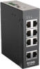
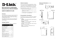
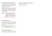
Connecting to Fiber Interfaces (SFP) Please prepare the LC connectors or SC connectors (with the use of an optional SC-to-LC adapter). These adapters are available with multimode, single mode, long-haul (for connections up to 120+ km) or in the form of special-application transceivers. For each fiber port there is a transmit (TX) and receive (RX) signal. Please make sure that the transmit (TX) port of the switch connects to the receive (RX) port of the other device, and the receive (RX) port of the switch connects to the transmit (TX) port of the other device when making your fiber optic connections. DANGER: Never attempt to view optical connectors that might be emitting laser energy. Do not power up the laser product without connecting the laser to the optical fiber and putting the cover in position, as laser outputs will emit infrared laser light at this point. Connecting the Power The switch can be powered using two power supplies (input range 12V - 58V). Insert the positive and negative wires into the V+ and V- contacts on the terminal block and tighten the wire-clamp screws to prevent the wires from being loosened. NOTE: The DC power should be connected to a properly-fused power supply. Connecting the Alarm Relay The alarm relay output contacts are in the middle of the DC terminal block connector as shown in the following figure. By inserting the wires and setting the DIP switch of the Port Alarm to "ON", the relay output alarm will detect any port failures, and form a short circuit. The alarm relay out is "Normal Open". DIP Switch Setting Pin No# Status Pin 1 ON OFF Pin 2 ON OFF 5-Port Model Enable the power alarm. Disable the power alarm. Enable broadcast storm rate limiting. Disable broadcast storm rate limiting. Pin No# Status Pin 1 ON OFF Pin 2 ON OFF 8-Port Model Enable broadcast storm rate limiting. Disable broadcast storm rate limiting. Enable the power alarm. Disable the power alarm. LED STATUS INDICATIONS LED Name Status Condition P1 P2 Alarm Solid green Off Solid green Off Solid red Off P1 power line has power. P1 power is disconnected or is not being powered. P2 power line has power. P2 power is disconnected or is not being powered. Power failure alarm triggered. No power failure alarm. Copper 1 to N port Link/Act Copper 1 to N port Speed SFP 1 to N port (N=0,1,2) Link/Act Solid green Blinking green Off Solid yellow Off Solid green Off Ethernet link up but no traffic is detected. Ethernet link up and there is traffic detected. Ethernet link down. A 100Mbps connection is detected. No link, or a10Mbps connection is detected. SFP port link up. SFP link down. Additional Information You can refer to the user manual or visit http://support.dlink.com/ for more support. Online Support If there are any issues that are not in the user manual, please visit http://support.dlink.com/ which will direct you to your appropriate local D-Link support website. Warranty Information Visit http://warranty.dlink.com/ to view the D-Link Warranty information. 3
-
 1
1 -
 2
2 -
 3
3 -
 4
4 -
 5
5 -
 6
6 -
 7
7 -
 8
8
 |
 |