D-Link DIS-200G-12PSW Quick Install Guide 1.05 WW - Page 5
Hardware Installation
 |
View all D-Link DIS-200G-12PSW manuals
Add to My Manuals
Save this manual to your list of manuals |
Page 5 highlights
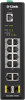
ENGLISH Rear Panel Connectors 1 Figure 5 requirements are investigated before mounting the DIS-200G, as access to the switch may be restricted once it has been installed. For safety caution details, please refer the HW installation guide which can be acquired from CD in the package. Caution! Hot surface! Do not touch! PRUDENCE! Surface chaude! Ne pas toucher! # Item Description 1 Power input This is used to connect an external power adapter to the switch. Table 5 Mounting the Switch on a DIN Rail Before beginning either mounting or removing the DIS-200G from a DIN rail, please ensure that the DIN rail is level and that the DIN rail mounting kit is installed correctly on the DIS-200G. Top Panel Connectors Use the following instructions to install the DIS-200G on a DIN rail: 1. With the back of the DIS-200G facing the DIN rail, lower the top part of the rail mounting kit onto the DIN rail. 2. Push the DIS-200G vertically down and rotate the bottom of the DIS-200G towards the DIN rail, to attach the switch to the DIN rail. 1 2 Figure 6 # Item Description 1 Switch ground This is used to connect the switch to ground. 2 Terminal block This is used to connect the switch to external power sources and relays. Table 6 Use the following instructions to remove the DIS-200G from a DIN rail: 1. Push the DIS-200G vertically down to create enough space at the bottom of the rail mounting kit to remove the DIS-200G from the DIN rail. 2. Rotate the DIS-200G upwards to remove the bottom of the rail mounting kit from the rail, and lift the DIS-200G upwards to remove the whole of the switch from the DIN rail. Hardware Installation Mounting the Switch on a Wall Before You Begin Observe the following precautions to help prevent shutdowns, equipment failures, and personal injury: The DIS-200G can be installed on a solid surface by using the included wall mounting plates attached to the back of the switch. It can also be mounted using the in-built screw hooks on the underneath • Install the DIS-200G in a cool and dry place. Refer of the switch. to the technical specifications in the user manual for the acceptable operating temperature and humidity ranges. • Leave at least 10 cm of space at the top, rear and bottom of the switch for ventilation. • Visually inspect the power connector and make sure that it is fully secured to the power cord. • Do not stack any devices on top of the switch. Using the Wall Mounting Brackets Use the following instructions to install the DIS-200G on a wall: 1. Remove the DIN rail mounting kit from the back of the DIS-200G (if present). 2. Align the cross-section of the mounting plates with the openings on the back of the switch and secure the plates to the switch with the included It is also recommended that power and grounding screws. 3
-
 1
1 -
 2
2 -
 3
3 -
 4
4 -
 5
5 -
 6
6 -
 7
7 -
 8
8 -
 9
9 -
 10
10 -
 11
11 -
12
-
13
-
14
-
15
-
16
 |
 |
